405
Installing the Video Interface (VIF3)
Installation on the Pa1X
Appendix
Installation on the Pa1X
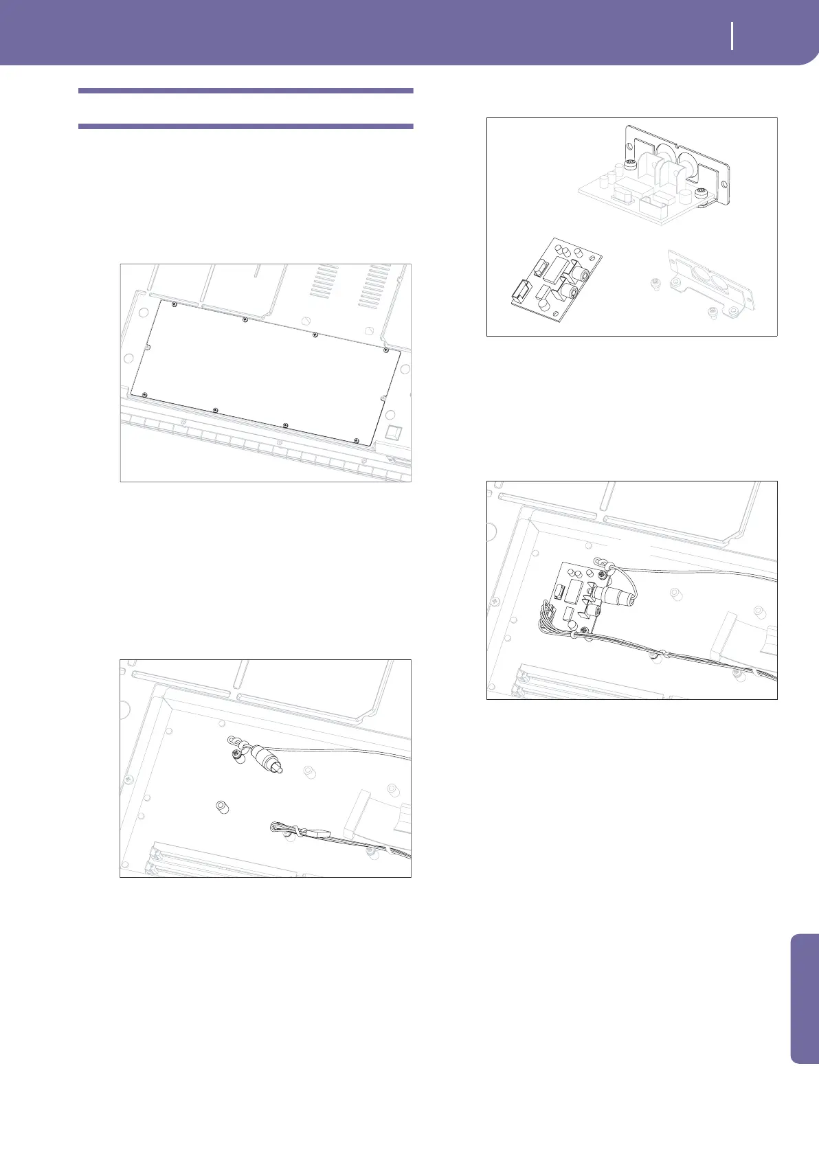
1. Turn the instrument upside down, and remove the eight
screws (d), to open the cover (c) and gain access to the
option compartment.
Note: Block any possible access to the inside of the instrument
during installation to prevent any items from falling inside. In
the event something does fall into the instrument, please
immediately contact your nearest Service Center.
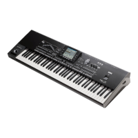
2. As you face the option compartment opening, locate the
area reserved for the video interface, i.e., the one with the
two small vertical spacers, the cable (e), secured by two
clips, and the cable (F), secured by the clip (C). Note how
the clip (C) is secured to one of the two vertical spacers by
means of the screw (b). Unscrew the screw (b) and remove
the clip (C). Then unfasten the cable (e) from the clip (C),
as shown in the diagram. Save the screw and the clip, you
will need them to complete the video interface installation.
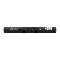
3. Note how the IC board (f) is joined to the support (g) by
means of the two screws (b). Unscrew the two screws (b) to
separate them. You will not need the removed support (g)
for the installation on the Pa1X, nevertheless we suggest to
save them for any future use. On the contrary, the removed
screws will be needed in the following step.
4. Secure the IC board (f) to the two vertical spacers using the
two screws (b), previously removed. Please remember to
re-insert the clip (C) at its original position. Connect the
terminal lug of the cable (F) to the corresponding connec-
tor on the IC board. Secure the cable to the clip (C). Finally,
connect the cable (e) to the IC board, and secure it using
the previously loosened clip (C).
5. Close and secure the compartment cover by reversing the
procedure described in step 1.
c
d
d
d
d
d
d
d
d
b+C
e
F
C
b
A
f
b
g
b
b
b+C
e
F
f
b
C