ELECTRICAL SYSTEM MLC650 SERVICE/MAINTENANCE MANUAL
3-42
Published 09-09-16, Control # 229-09
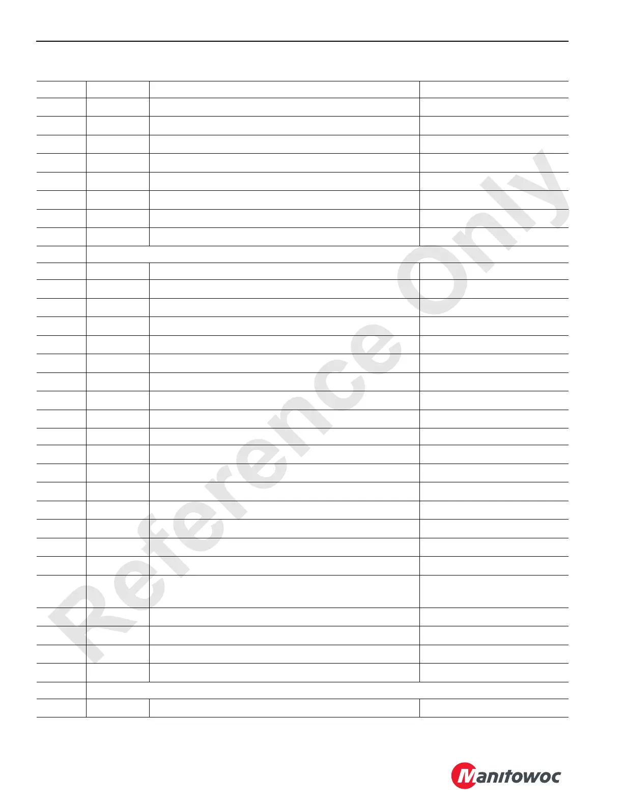
Table 3-16. IOLC31 Test Voltages
Pin I/O Network Function Voltages
PC1-1 GND Ground (from ground stud on rotating bed)
0V
DC
PC1-2 KL15 Control Module Ignition Power (from engine run switch)
0V
DC
Open, 24 V
DC
Closed
PC1-3 ID01 Not Used—For Possible Future Expansion
0V
DC
PC1-4 ID02 Not Used—For Possible Future Expansion
0V
DC
PC1-5 OPH6A18 Drum 0 Spool In Solenoid
0V
DC
Off, 24 V
DC
On
PC1-6 OPH6A19 Drum 0 Spool Out Solenoid
0V
DC
Off, 24 V
DC
On
PC1-7 OPH6A20 Not Used—For Possible Future Expansion
0V
DC
PC1-8 OPH6A21 Not Used—For Possible Future Expansion
0V
DC
PC1-9 No connection
PC1-10 CAN1_H CAN Bus C—High Not Applicable
PC1-11
+U
B
Supply Power for Control Module Outputs
24 V
DC
PC1-12
+U
E
Control Module Battery Power
24 V
DC
PC1-13 ID03 Not Used—For Possible Future Expansion
0V
DC
PC1-14 ID04 Not Used—For Possible Future Expansion
0V
DC
PC1-15 ID05 Not Used—For Possible Future Expansion
0V
DC
PC1-16 ID06 Not Used—For Possible Future Expansion
0V
DC
PC1-17 IDF15 Not Used—For Possible Future Expansion
0V
DC
PC1-18 IMID2 Module Identifier Input (from ground stud on rotating bed)
0V
DC
PC1-19 CAN1_L CAN Bus C—Low Not Applicable
PC1-20
+U
B
Supply Power for Control Module Outputs
24 V
DC
PC1-21 ID07 Not Used—For Possible Future Expansion
0V
DC
PC1-22 ID08 Not Used—For Possible Future Expansion
0V
DC
PC1-23 ID09 Not Used—For Possible Future Expansion
0V
DC
PC1-24 ID10 Not Used—For Possible Future Expansion
0V
DC
PC1-25 ID11 Not Used—For Possible Future Expansion
0V
DC
PC1-26 IDF16 Not Used—For Possible Future Expansion
0V
DC
PC1-27 IACV17 Drum 5 Pressure Transducer
4mA @ 0psi
20 mA @ 7,500 psi
PC1-28 IMID4 Module Identifier Input (from ground stud on rotating bed)
0V
DC
PC1-29 IMID3 Module Identifier Input (from ground stud on rotating bed)
0V
DC
PC2-1 ID12 VPC-MAX Shorting Wire
24 V
DC
PC2-2 ID13 VPC Tray Shorting Plug
24 V
DC
PC2-3 No Connection
PC2-4 IACV18 Drum 3 Pressure Transducer
0V
DC
Off, 24 V
DC
On

 Loading...


