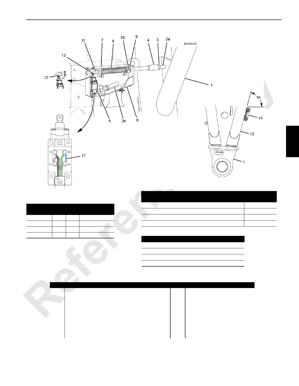
Item Description Item Description
1 Boom Butt 9 Spring Washer
2a Adjusting Rod for 83° Boom Angle—133 mm (5.25 in) 10 Spring Pin
2b Adjusting Rod for 85° Boom Angle—105 mm (4.125 in) 11 Actuator Rod
3 Jam Nut 12 Over-Travel
4 Coupling (part of actuator rod) 13 Switch Closed
5 Limit Switch 14 Digital Protractor-Level
6 Boom Stop Switch Unit 15 Boom Butt Bottom Chord
7 Spring Washer 16 Digital Level Angle
8 Spring 17 Blue Jumper Wire
View D
LIMIT SWITCH WIRING
Receptacle
Switch
Terminals
Function
Black 13 Ground
Green 14 Maximum Angle
White 21 24 VDC Supply
Blue 14 22 Jumper
View C
RIGHT SIDE OF BOOM BUTT
Maximum Switch Boom Angle
Digital Level
Angle (16)
84.5° —Boom only with VPC-MAX
73.57°
86.4° —Boom with Luffing Jib and without VPC-MAX
75.47°
86.4° —Boom with Luffing Jib and VPC-MAX
75.47°
86.4° —Boom only with VPC
75.47°
View A
SWITCH OPENED
View B
SWITCH CLOSED
FIGURE 4-3
Maximum Boom Angle
83° —Boom only with VPC-MAX
85° —Boom with Luffing Jib and without VPC-MAX
85° —Boom with Luffing Jib and VPC-MAX
85° —Boom only with VPC