Manitowoc Published 09-09-16, Control # 229-09 3-27
MLC650 SERVICE/MAINTENANCE MANUAL ELECTRICAL SYSTEM
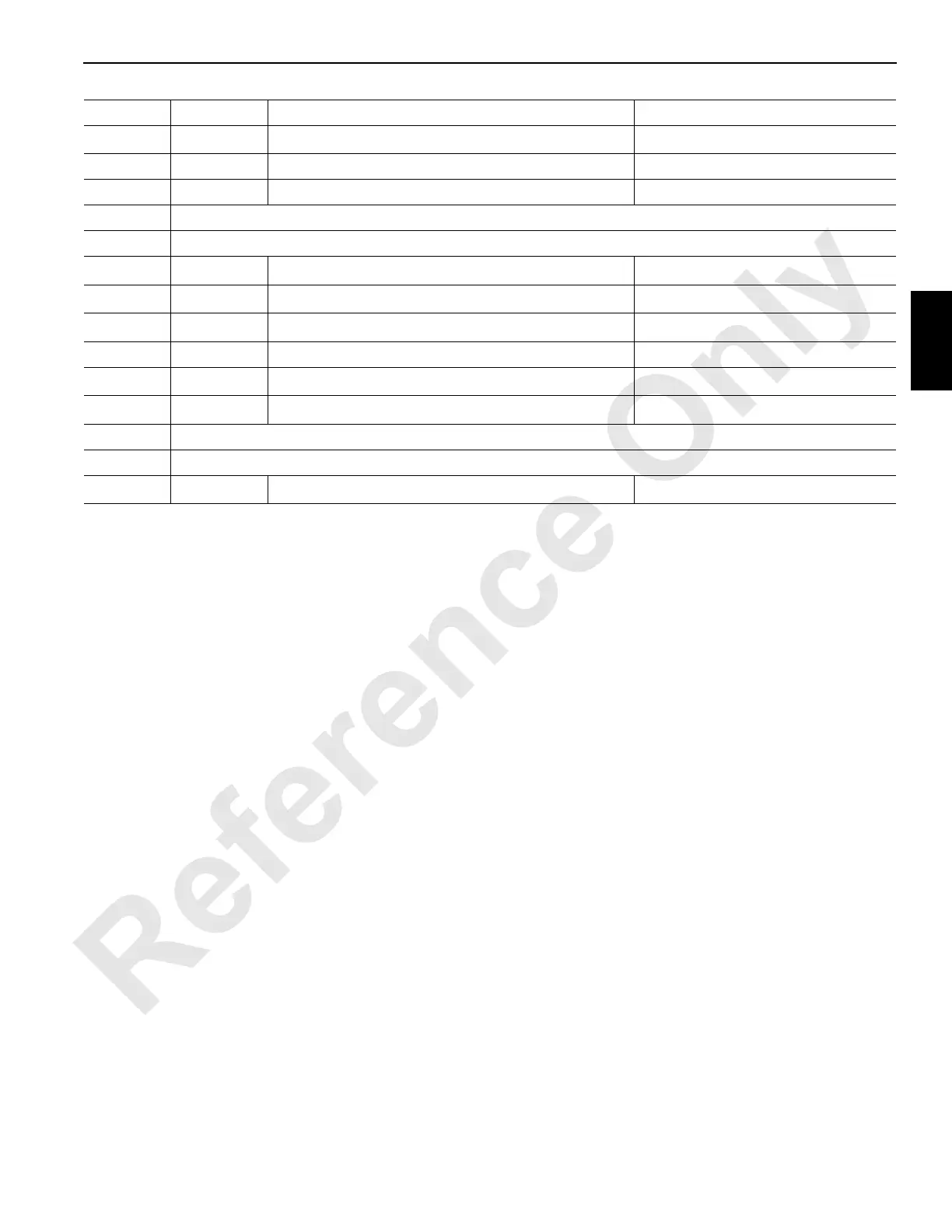
PD-29 GND Ground (from load center)
0V
DC
PD-30 CAN1_L CAN Bus D—Low Not Applicable
PD-31 CAN1_H CAN Bus D—High Not Applicable
PD-32 No Connection
PD-33 No Connection
PD-34 IMID2 Module Identifier Input (ground from load center)
0V
DC
PD-35 ID7 EUBP Block-Up Limit Switch 1
0V
DC
Open, 24 V
DC
Closed
PD-36 ID8 EUBP Block-Up Limit Switch 2
0V
DC
Open, 24 V
DC
Closed
PD-37 IACV14 EUBP Wind Speed Sensor 0 to 20 mA
PD-38 IACV15 Lower Boom Point Load Link
0V
DC
Open, 24 V
DC
Closed
PD-39 IACV16 Not Used—For Possible Future Expansion
0V
DC
PD-40 No Connection
PD-41 No Connection
PD-42 ID10 Not Used—For Possible Future Expansion
0V
DC
Pin I/O Network Function Voltages