CHARGING & STARTING SYSTEM
90-857046R1 NOVEMBER 2001 Page 2B-9
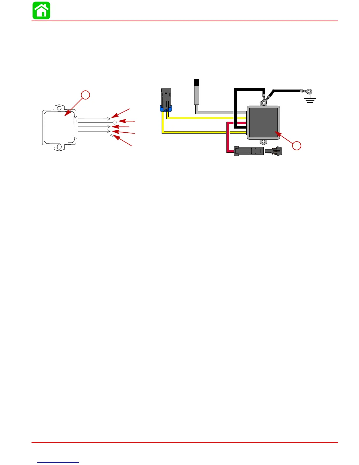
Rectifier/Regulator (P/N 854514) Diode Test
Analog Meter
NOTE: Voltage regulator/rectifier specifications are given for informational purposes only,
use the appropriate troubleshooting techniques previously mentioned to find the faulty com-
ponent in the charging system.
Blk = Black
Gry = Gray
Red = Red
Yel = Yellow
YEL
GRY
YEL
RED
BLK
YEL
GRY
YEL
RED
BLK
b
a
a-S/N OG960499 and Below
b-S/N OG960500 and Up
DIODE TEST:
1. Set Ohm meter to R X 10 scale.
2. Connect Red (+) meter lead to RED regulator lead.
3. Connect Black (–) meter lead to either YELLOW regulator lead.
TEST RESULTS: 100 - 400 OHMS
DIODE TEST:
1. Set Ohm meter to R X 1k scale.
2. Connect Black (–) meter lead to RED regulator lead.
3. Connect Red (+) meter lead to YELLOW regulator lead. Test. Then change Red (+) me-
ter lead to the other YELLOW regulator lead for 2ND test reading.
TEST RESULTS (1ST READING): 20,000 to ∞ OHMS
TEST RESULTS (2ND READING): ∞ OHMS (No needle movement)
SCR TEST:
1. Set Ohm meter to R X 1k scale.
2. Connect Red (+) meter lead to regulator case.
3. Connect Black (–) meter lead to one YELLOW regulator lead. Test. Connect Black (–)
meter lead to the other YELLOW lead.
TEST RESULTS (BOTH TESTS): 8,000 - 15,000 OHMS (8k - 15K)
TACHOMETER CIRCUIT TEST:
1. Set Ohm meter to R X 1k scale.
2. Connect Red (+) meter lead to GREY regulator lead.
3. Connect Black (–) meter lead to regulator case.
TEST RESULTS: 10,000 - 50,000 OHMS (10k - 50k)