CHARGING & STARTING SYSTEM
Page 2B-10 90-857046R1 NOVEMBER 2001
Digital Meter
NOTE: Voltage regulator/rectifier specifications are given for informational purposes only,
use the appropriate troubleshooting techniques previously mentioned to find the faulty com-
ponent in the charging system.
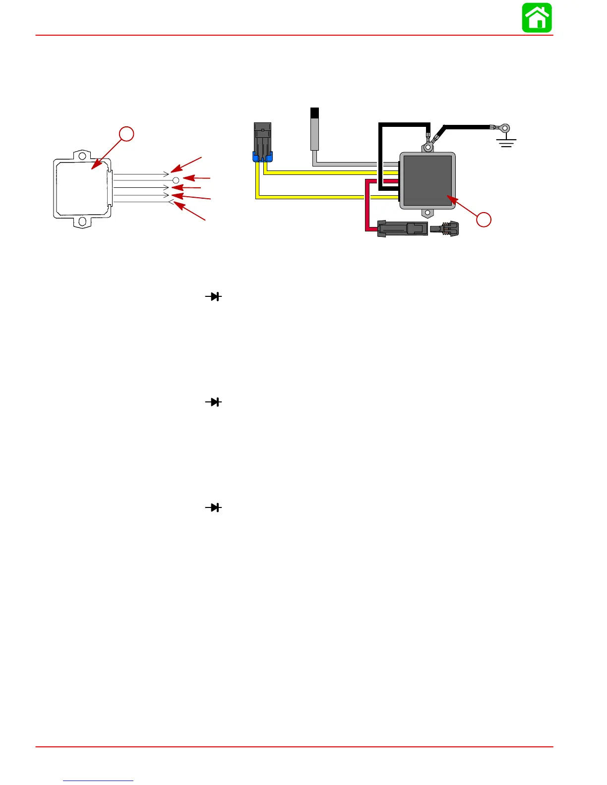
Blk = Black
Gry = Gray
Red = Red
Yel = Yellow
YEL
GRY
YEL
RED
BLK
YEL
GRY
YEL
RED
BLK
b
a
a-S/N OG960499 and Below
b-S/N OG960500 and Up
DIODE TEST:
1. Set meter to
.
2. Connect Black (–) meter lead to RED regulator lead.
3. Connect Red (+) meter lead to either YELLOW regulator lead.
TEST RESULTS:
0.4-0.8 V
DIODE TEST:
1. Set meter to
.
2. Connect Red (+) meter lead to RED regulator lead.
3. Connect Black (–) meter lead to either YELLOW regulator lead.
TEST RESULTS (1ST READING):
∞ or OUCH or OL
SCR TEST:
1. Set meter to
.
2. Connect Black (–) meter lead to regulator case.
3. Connect Red (+) meter lead to either YELLOW regulator lead.
TEST RESULTS (BOTH TESTS):
1.5 V - ∞ or OUCH or OL
TACHOMETER CIRCUIT TEST:
1. Not measurable with digital meter.

 Loading...