EasyManuals Logo

Mercury 40 FourStroke User Manual

Mercury 40 FourStroke
584 pages
To Next Page IconTo Next Page
To Previous Page IconTo Previous Page
Page #497 background imageLoading...
Page #497 background image
BIGFOOT GEAR HOUSING
90-857046R1 NOVEMBER 2001 Page 6B-31
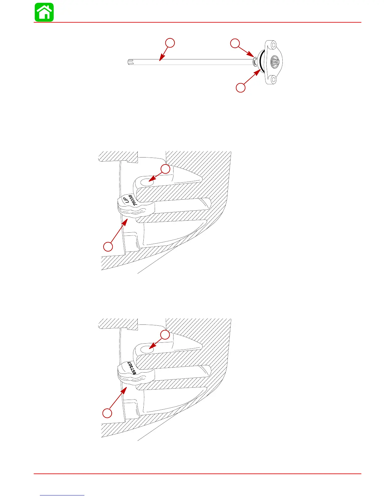
5. Assemble components as shown.
53928
a
b
c
a- Shift Shaft
b- “E” Clip
c- Shift Shaft Bushing
6. Install shift cam. Align hole in shift cam with shift shaft pilot bore in gear housing.
60 Bigfoot, 75/90/100/115/125 (2-Stroke)
51117
a
b
a- Shift Cam (marked with “UP” and part number)
b- Shift Shaft Pilot Bore
60 Bigfoot, 75/90/100/115/125 (2-Stroke) & 75/90/115EFI (4-Stroke)
51117
a
b
a- Shift Cam (marked with part number only)
b- Shift Shaft Pilot Bore

Table of Contents

Questions and Answers:

Question and Answer IconNeed help?

Do you have a question about the Mercury 40 FourStroke and is the answer not in the manual?

Mercury 40 FourStroke Specifications

General IconGeneral
BrandMercury
Model40 FourStroke
CategoryOutboard Motor
LanguageEnglish

Related product manuals