TILLER HANDLE
Page 7B-10 90-857046R1 NOVEMBER 2001
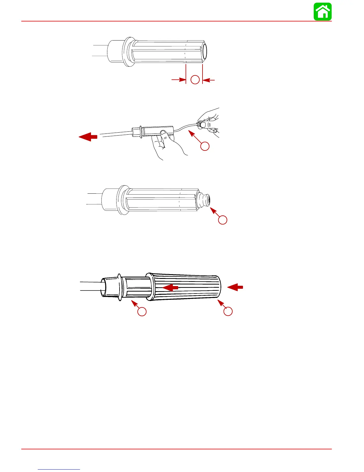
5. Check to make sure tiller tube is recessed in the end of the handle 7/8 in. (22.2mm).
7/8 in. (22.2mm)
a
a-7/8 in. (22.2 mm)
6. Insert the engine stop switch harness through the tiller tube.
a
a-Engine Stop Switch Harness
7. Place the stop switch into end on handle.
a
a-Stop Switch
8. Align the grooves inside the rubber grip with the ridges on the handle. Push the rubber
grip onto the handle.
NOTE: Applying a soap/water solution to the inside of the rubber grip will ease installation.
a
b
a-Rubber Grip
b-Handle

 Loading...