NICE3000
new
User Manual
6 System Commissioning and Functions
- 159 -
◆
Recommended Method
1. Method description
Table 6-12 Setting of recommended opposite door control method
Type Door Control Mode
Parameter Setting
Service
Floor
HCB Address
Setting
Operation Box
CCB Wiring
Mode
Selection
Other
Parameters
Mode 1
Simultaneous
control
FC-04 = 0
Fb-00 = 2,
F8-16 = N
(N > F6-00)
20
HCB address of
front door: 1–20
HCB address of
back door: N to
N+20
The CCB of front
door is connected
to CN7 on the
CTB.
The CCB of back
door is connected
to CN8 on the
CTB.
Mode 2
Hall call
independent, car
call simultaneous
FC-04 = 1 Same as mode 1 20
Mode 3
Hall call
independent, car
call manual control
FC-04 = 2
F6-40 Bit4 = 1
Same as mode 1 20
Mode 4
Hall call
independent, car
call independent
FC-04 = 3 Same as mode 1 20
In mode 3, the car door to open is controlled as follows:
● Control by button
Connect the button to JP16 on the CCB, and set F6-40 Bit2 to 1.When the button indicator is steady ON, only the
front door opens; when the button indicator is steady OFF, only the back door opens
● Control by switch
Connect the switch to JP20 on the CCB, and set F6-40 Bit15 to 1. When JP20 is ON, only the front door opens;
when JP20 is OFF, only the back door opens.
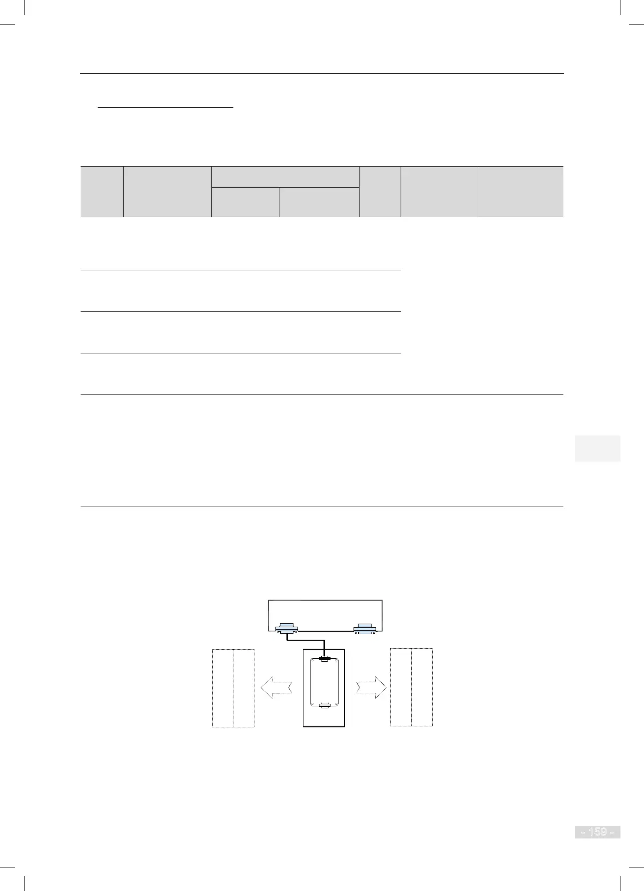
2. CCB wiring
For modes 1, 2, and 3, either a single operation box or double operation boxes are supported. The
CCB wiring is shown in the following gures.
Figure 6-25 CCB wiring of single operation box
MCTC-CTB-A
CN7
CN8
MCTC-
CCB-A
Front door
Control
Control
Front
operation box
Back door