NICE3000
new
User Manual
4 Peripheral Devices and Options
- 85 -
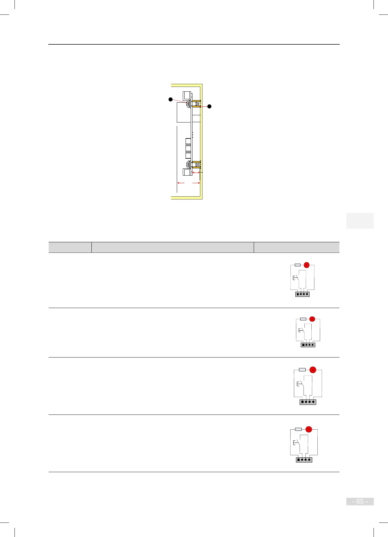
The following gure shows the installation method of HCB-B.
Figure 4-19 Installation method of HCB-B
MCTC-HCB-B
8.8
26.4
Unit: mm
1 - Plastic support higher than 1 cm
2 - Combination screw M4x10
1
2
The following table describes the input and output terminals of HCB-B.
Table 4-14 Input and output terminals of HCB-B
Terminal Name Function Terminal Wiring
JP1
Interface for the elevator lock switch
Pins 2 and 3 are for switch input. Pins 1 and 4 are for output of
the elevator lock indicator.
1 2 3 4
Elevator lock indicator
Elevator
lock button
JP2
Interface for the re emergency switch
Pins 2 and 3 are for switch input. Pins 1 and 4 are for output of
the re emergency indicator.
1 2 3 4
Fire emergency button
Fire emergency
button
JP3
Interface for the up call button and indicator
Pins 2 and 3 are for up call input. Pins 1 and 4 are power supply
for the up call indicator.
1 2 3 4
Up call indicator
Up call button
JP4
Interface for the down call button and indicator
Pins 2 and 3 are for down call input. Pins 1 and 4 are power
supply for the down call indicator.
1 2 3 4
Down call indicator
Down call
button