4 Peripheral Devices and Options NICE3000
new
User Manual
- 86 -
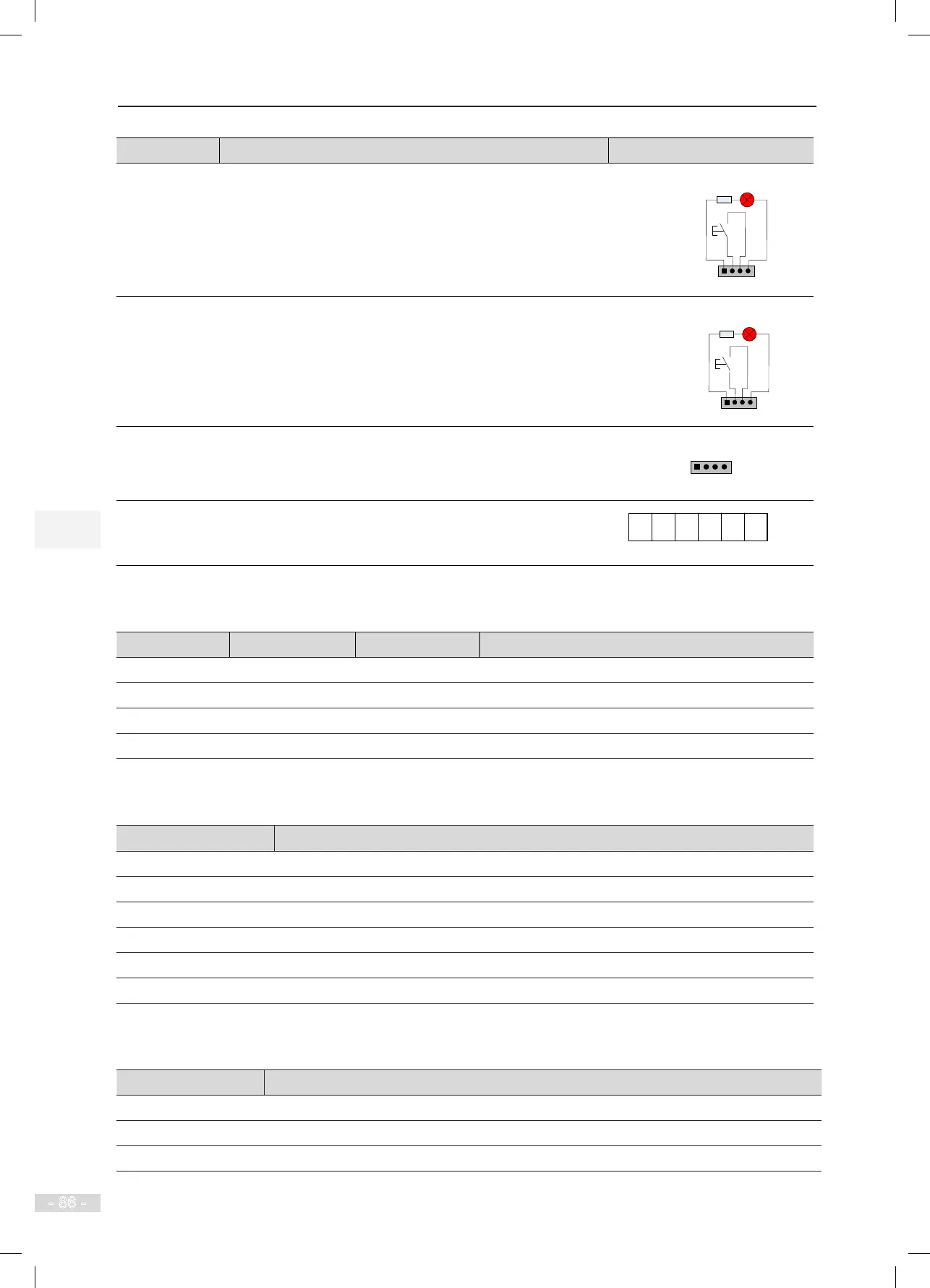
Terminal Name Function Terminal Wiring
JP5
Interface for the disability up call button and indicator
Pins 2 and 3 are for up call input. Pins 1 and 4 are power supply
for the up call indicator.
1 2 3 4
Disability up call
indicator
Disability up
call button
JP6
Interface for the disability down call button and indicator
Pins 2 and 3 are for down call input. Pins 1 and 4 are power
supply for the down call indicator.
1 2 3 4
Disability
down call
indicator
Disability
down
call button
CN1
Modbus communication and power supply terminal
Pins 2 and 3 are for Modbus communication. Pins 1 and 4 are
for DC power supply.
CN2
Relay output
For the denition of the pins, see Table 4-15.
The HCB-B provides four relay outputs, K1, K2, K3, and K4, provided by CN2 terminals.
Table 4-15 Relay output and pin denition of CN2
Relay CN2 Pin Common
Function Description
K1 A1 AM Up arrival indicator
K2 A2 AM Down arrival indicator
K3 B1 BM Up arrival gong
K4 B2 BM Down arrival gong
The DIP switch S1 is used to set the oor address of the HCB-B, as described in the following table.
Table 4-16 Floor address setting by S1
S1
Floor Address Setting, Range: 0–63
S1.1 Floor address selection Bit0
S1.2 Floor address selection Bit1
S1.3 Floor address selection Bit2
S1.4 Floor address selection Bit3
S1.5 Floor address selection Bit4
S1.6 Floor address selection Bit5
The DIP switch S2 is used to select the function of the HCB-B, as described in the following table.
Table 4-17 S2 description
S2 Function
S2.1 Modbus termination resistor setting
S2.2 HCB-B function selection
S2.3 HCB-B function selection