SECTION 5
DISASSEMBLY AND ASSEMBLY
111
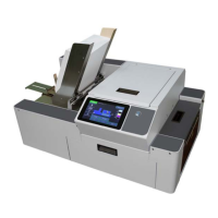
7. Remove (1) screw [G] securing the Media Guide Base Plate to
the Side Frame.
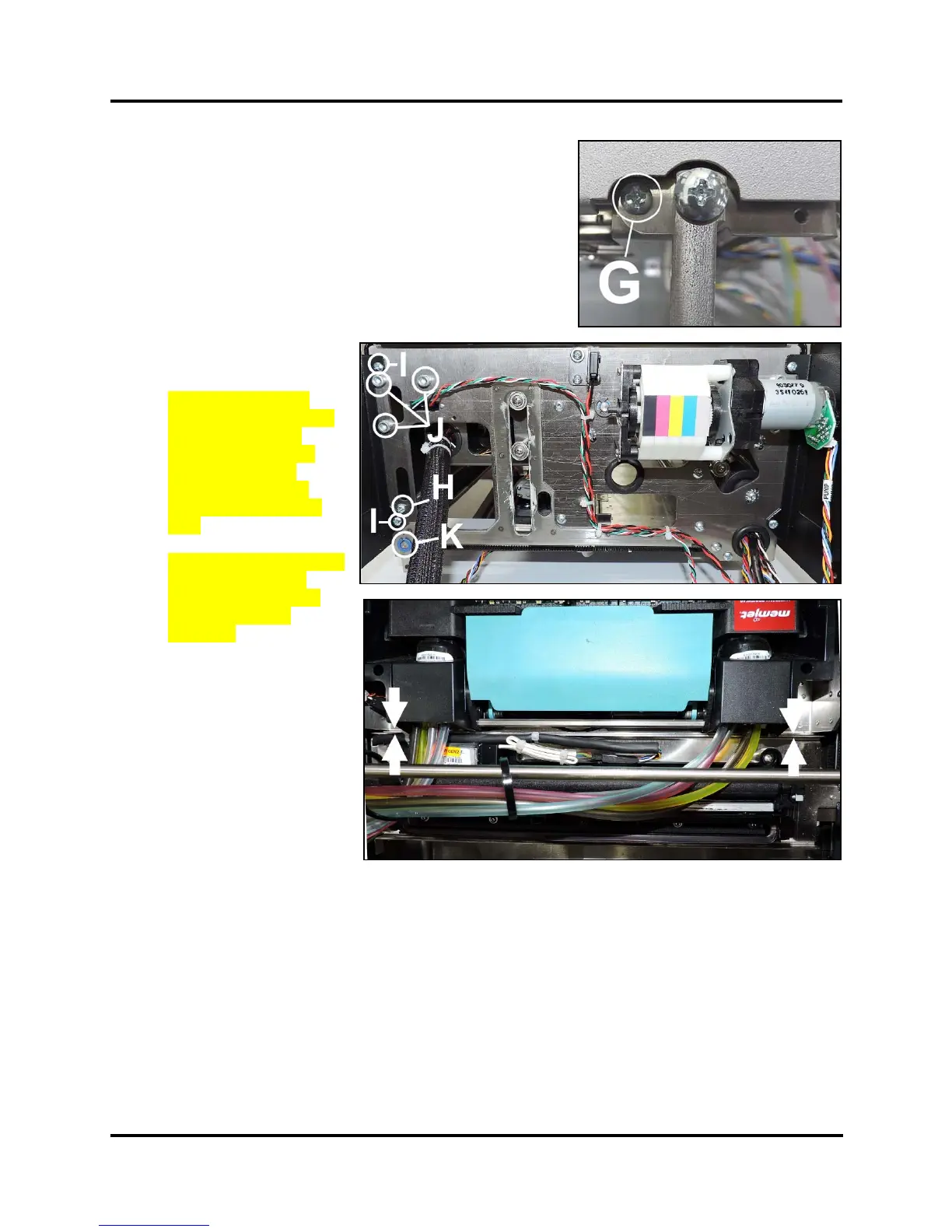
8. Remove (1) screw [H] securing the Support Rod.
Remove (2) screws [I] securing the Top Assembly Side Panels
(2 screws per side).
Loosen (3) screws [J] securing the Top Supports
(3 screws per side.)
9. Pull the Side Frame away from the Top Assembly enough to
release the Service Station Motor Drive Shaft Assembly [K].
10. Remove the Belt. Note how
the belt is routed through
the Pulleys.
11. NOTE: Check/adjust
Positioning Belts tension.
See “Service Station
Position Belts Tension
Adjustment” in the
Adjustments Section.
System Test: Press Sled
Test.
IMPORTANT: Make sure
the Service Station is
installed parallel to the
Printhead Locator
Assembly.
Check this by lowering
Printhead Locator
Assembly to its lowest
point and pushing the
Service Station Assembly
up against it [see arrows].
They should meet flush
with no gaps at either end.
 Loading...


