Transformer
6 - 25
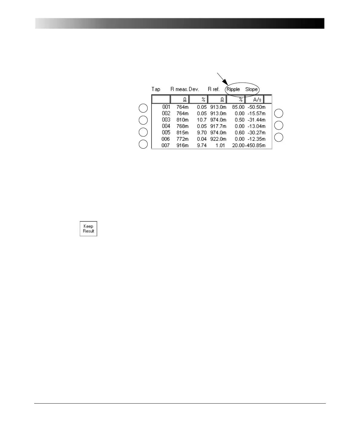
Figure 15:
Measurement table with
results of tap changer
and winding resistance
test
In Figure 15, you notice significantly higher values for ripple and slope in line 7.
Compared to the properly functioning tap changer of line 5, at this transformer
the ripple is about 30 times and the slope about 15 times higher.
Note: The measurement results shown in Figure 15 were taken from a
220/110kV 220MVA transformer by injecting a test current of 5A DC.
Note: The steps of this procedure are explained without explicitly outlining
how to change/edit the tap number.
However, you can to do so each time K
EEP RESULT was pressed to
save the current test results and a new line was added to the
measurement table. It is done in the same way as explained in
”Measuring the winding resistance of the taps” on page 23 of this
chapter.
1
2
3
4
5
7
6
For the tap changer test, the last 2 columns of the table are relevant.

 Loading...


