CPC 100 V1.41
2 - 4
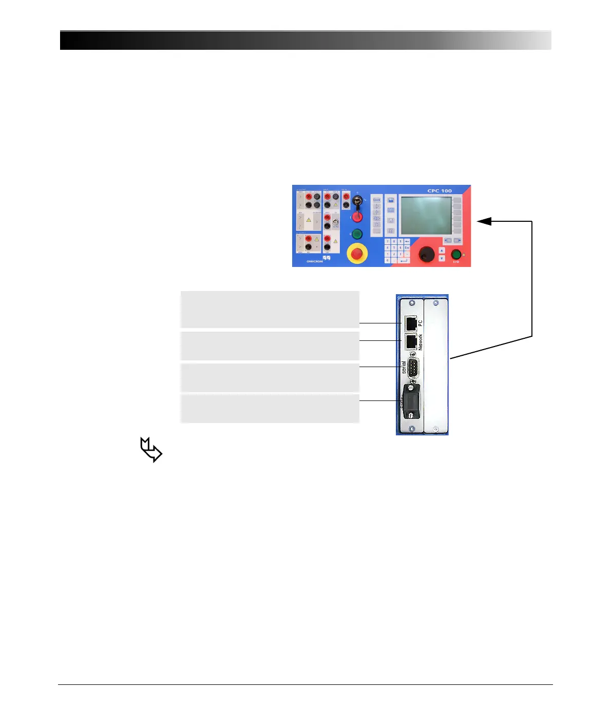
ePC Interfaces
The ePC interfaces are located on the right-hand side of the CPC 100 housing.
The PC and network interfaces differ depending on the CPC 100 version as
described below.
Figure 3:
ePC interfaces of the
CPC 100 V0
1. For more information on the PC and network interfaces, see ”CPC 100 in a
Network” on page 11-1.
2. For the pin assignment of the RS232 serial interface connector, see ”ePC
Interfaces” on page 16-29.
3. The connector for external safety functions allows connecting:
• an external Emergency Stop or "dead man" button
• an external "test start/stop" push-button
• external I/O warning lights.
The attached plug contains a jumper for the emergency stop or "dead man"
function, and as long as the plug is placed on the connector, these functions
are bridged. If the plug is removed, emergency stop is active.
For the plug’s pin assignment and a wiring scheme, see ”Connector for
External Safety Functions” on page 16-31.
RJ-45 socket for connecting CPC 100 to either
a PC’s Ethernet network card or a notebook’s
PC NIC (⇒ Glossary)
RJ-45 socket for connecting CPC 100 to a PC
network hub
Serial interface connector for connecting
optional CP TD1 test set
Connector for external safety functions (see item
3 below)

 Loading...


