CPC 100 V1.41
7 - 20
In an earthing system with several grounding rods it may be of interest to
measure the resistance of a single rod. To do so, disconnect the rod to be
measured from the earthing system, and feed current through the rod into the
grounding system (as shown in Figure 12 for rod 2). The voltage is measured
directly at the current supply points.
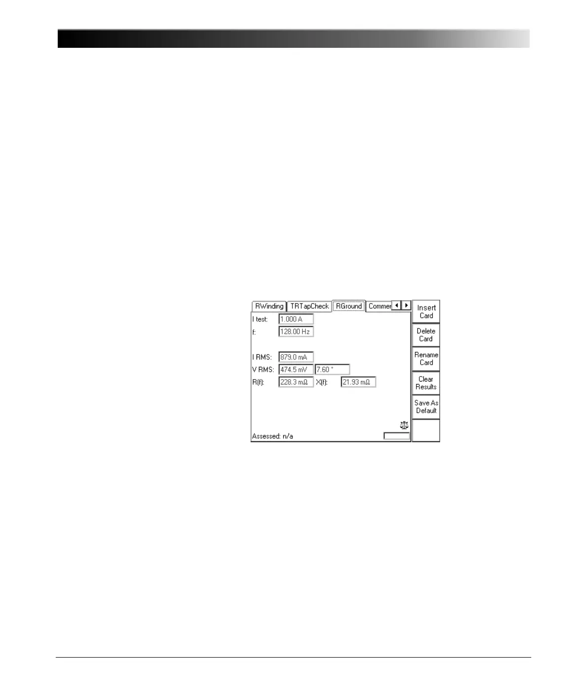
Test settings
Figure 13:
RGround test card with
test results
Navigate to the parameter fields, and enter the values according to your test
requirements:
Note: The resistance measured is only an approximation of the actual
grounding resistance because the parallel resistance of all other
ground rods is measured, too. If one electrode is too close by the
measured electrode, values by far too small could be measured.
In order to obtain a more accurate result, the method shown in Figure
9 on page 7-15 can be used.
Itest: nominal test current
f: frequency of test current.
Select a frequency other than the 50 or 60Hz mains frequency
to prevent interferences by stray earth currents (caused by the
mains frequency and their harmonics). The value can be varied
between 15 ... 400Hz. Default is 128Hz.

 Loading...


