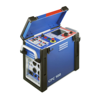
CPC 100 V1.41
8 - 10
Press the I/O (test start/stop) push-button to start the output of the sequence of
states (or the single state, if only one was defined).
In the states table, the first state is highlighted and its values are output. The
measurement table displays the measured values, and updates them as well as
the indication of the binary input’s signal status with an interval of approx. 0.5s.
At the end of each state - either after the state time has elapsed at the transition
to the next state, or at the occurrence of the state’s trigger signal - the values in
the measurement table are once more updated.
V I For AC: Z or R, X
Impedance Z (magnitude in
Ω and phase angle ϕ in °) or R
and X in
Ω.
For DC: R
Resistance R (in
Ω)
else "n/a"
VI
For AC: P, Q, S
Real power P (in W) and cos
ϕ, apparent power S (in VA)
and cos
ϕ, reactive power Q (in var) and cosϕ.
For DC: P
Real power P (in W)
else "n/a"
V I Rs, Ls or Rp, Cp:
Resistance R and either inductance Ls in H (series
equivalent circuit) or capacity Cp in F (parallel equivalent
circuit).
This is just another representation of the impedance Z
measurement; Z
is displayed in its components.
Using Rs, Ls, the impedance is given by:
Z
=Rs+jω Ls, where ω =2π f and the set frequency is
used for the calculation.
Using Rp, Cp, the admittance is given by:
1/Z
=1/Rp+jω Cp, where ω =2π f and the set
frequency is used for the calculation.
Measured
quantities
Display of calculated value in measurement table
(m1) (m2)

 Loading...