CPC 100 V1.41
8 - 20
Next, set the ramp(s) parameters, that is, the parameters that apply to this
particular ramp only. Each line of the ramps table represents one ramp.
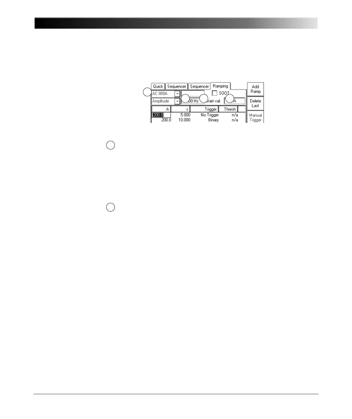
Figure 16:
Step 2 - Set the ramp
parameters
Turn the handwheel to set the focus onto the ramps table’s first cell; in
Figure 16 above it is the output current. Then press the handwheel. The
cell turns into an entry field. Now set the output current value of your
choice by turning the handwheel, or use the number keys of CPC 100
soft-touch keyboard. Press E
NTER or the handwheel to acknowledge
your setting and move to the next table cell by turning the handwheel.
Note that the units of the ramps table (the table’s columns) depend on
the selected output range.
Duration of ramp, that is, the time this particular ramp sweeps the
selected signal from the start to the end value.
After this period of time the ramp terminates and the series continues
with the next ramp (if any).
If a trigger signal occurs before this time has elapsed, the currently
running ramp terminates and the series continues with the next ramp. If
"SOOT" is selected, the trigger signal terminates the complete series of
ramps.

 Loading...


