Precautions for Correct Use
You must attach either a jumper or some other safety-rated devices (typically E-STOP buttons)
to the SCPU connector in order for the AMR to function.
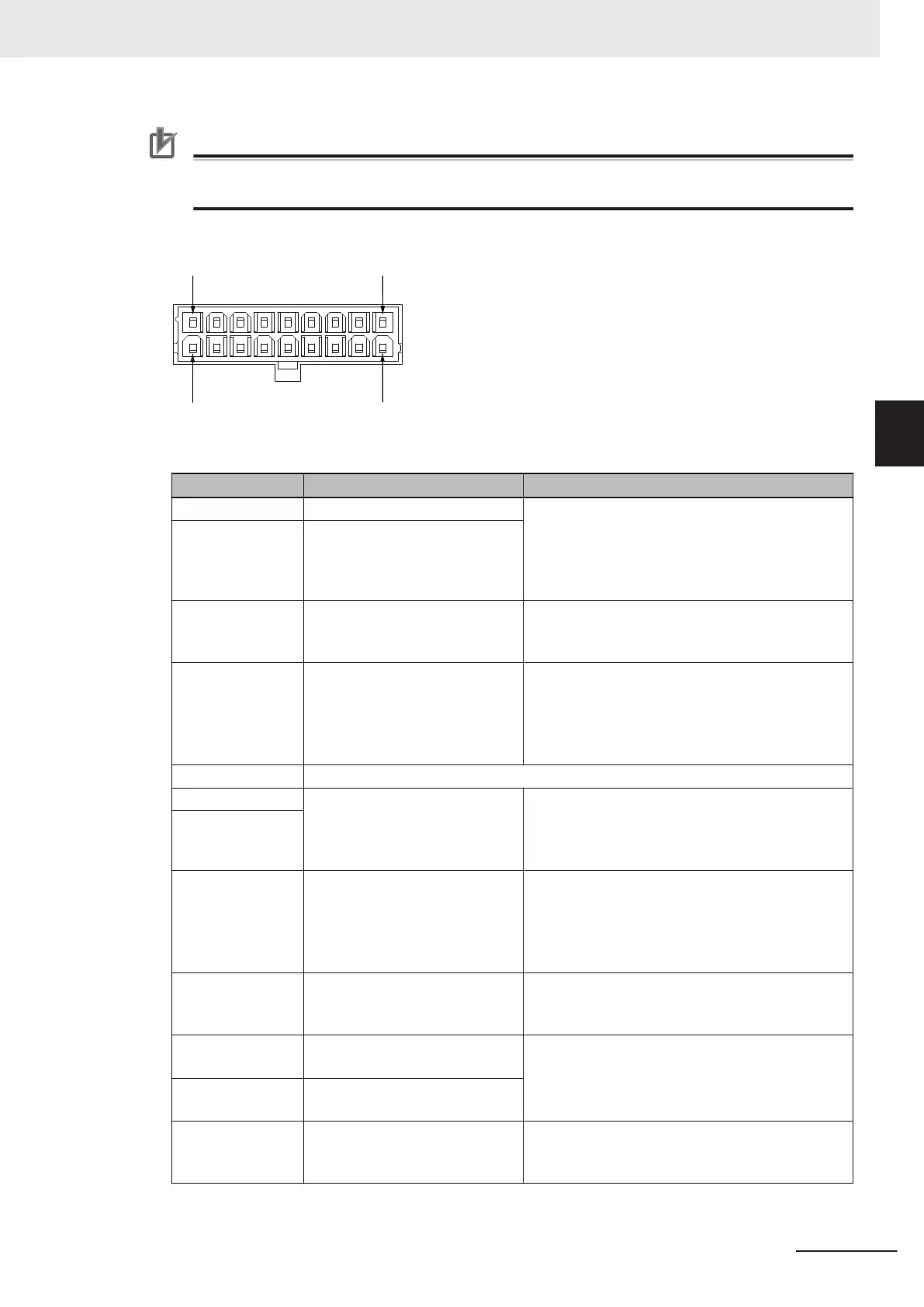
The following figure shows the pin arrangements for the SCPU connector on the AMR.
The information in the table below describes the signal designations for the SCPU connector.
Pin Number Item Description
1 Emergency stop channel 1 input Dual-channel emergency stop circuit inputs.
Monitored for simultaneous switching within 500
ms.
Refer to 4-18 Emergency Stop on page 4-36 for
more information.
2 Emergency stop channel 2 input
3 Safety output 1 Dual-channel safety output.
Refer to 4-18 Emergency Stop on page 4-36 for
more information.
4 Protective stop channel 1 input Dual-channel protective stop circuit input.
Monitored for simultaneous switching within 500
ms.
Refer to 4-19 Protective Stops on page 4-38 for
more information.
5 Ground
6 24 VDC For use with alternative safety zone / protective
stop circuits.
Do not connect external loads to 24 VDC termi-
nals.
7
8 Alternate safety zone input 1 Dual-channel alternate safety zone circuit input.
Monitored for simultaneous switching within 500
ms.
Refer to 4-25-2 Alternate Safety Laser Scanner
Zones on page 4-73 for more information.
9 No motion output 1 Dual-channel no motion output.
Refer to 4-30 No Motion Signals on page 4-79 for
more information.
10 Emergency stop channel 1 out-
put
Dual-channel emergency stop circuit outputs.
Refer to 4-18 Emergency Stop on page 4-36 for
more information.
11 Emergency stop channel 2 out-
put
12 Safety output 2 Dual-channel safety output circuit.
Refer to 4-18 Emergency Stop on page 4-36 for
more information.
3 Installation
3-21
AMR (Autonomous Mobile Robot) MD-series Platform User's Manual (I681)
3-5 Electrical Connections
3
3-5-1 User Connections Area

 Loading...


