1 Turn the AMR OFF.
2 Place the Main Disconnect Switch in the OFF position.
3 Remove the User Connections area cover, the Right and the Left Skins. Refer to 6-11-1 Re-
moving and Replacing Skins on page 6-17 for more information.
4
Prepare the M12 A coded power cable by trimming excess length and then stripping insulation
to prepare it for ferrule attachment.
5
Insert the brown wire into the ferrule and crimp the ferrule using the crimper. Repeat for the
blue wire.
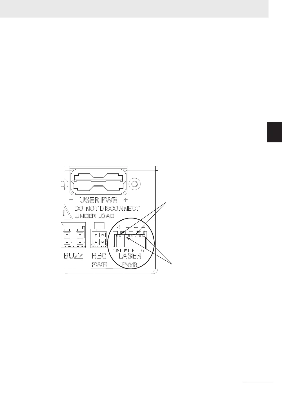
6 Connect the negative blue wire connector to the negative terminal in the Laser PWR connector
on the Connector Panel.
7 Connect the positive brown wire connector to the positive terminal in the Laser PWR connector
on the Connector Panel.
Connect Brown Wires
Connect Blue Wires
8
Connect the other end of the A coded M12 power cable to the A coded M12 power connector
on the rear of the Side Laser.
3 Installation
3-41
AMR (Autonomous Mobile Robot) MD-series Platform User's Manual (I681)
3-11 Side Laser Installation
3
3-11-2 Side Laser Wiring Procedure

 Loading...


