41 / 374
SOCT User Manual Version 10.0 rev. A
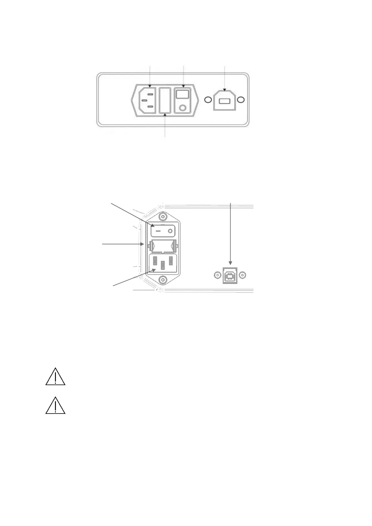
All sockets and plugs are different, so it is not possible to connect plugs improperly. The
figure below shows the rear panel view of SOCT.
Figure 3. Rear panel of the REF 155 and 156 series device
Figure 4. Rear panel of the REF 190 and 193 series device
First connect USB cable, in the next step connect power supply cables.
The power switch has two positions: I – the device is ON, O the device is Off.
NOTE: To remove power from the device turn OFF the power switch (Position O) or
unplug the power cord from the wall or from the device.
NOTE: Regarding EMC (Electro-magnetic compatibility) standards all signal cables
have to be put together.