Supplementary Functions
13-16
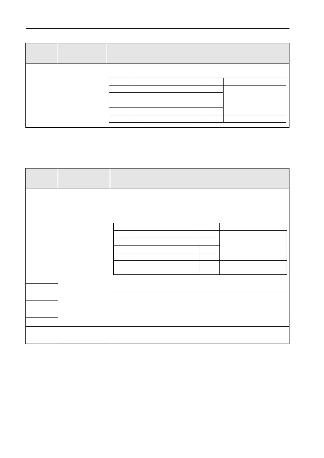
Unit
memory no.
(Hex)
Name Description
UM 00240
Pulse count enable
flag
The pulse input value will be changed to the set pulse count when the
corresponding bit for each axis is set to 0 from 1.
bit Name Default Description
0 1st axis pulse count enabled 0
0: Pulse count enabled
1: Pulse count disabled
1 2nd axis pulse count enabled 0
2 3rd axis pulse count enabled 0
3 4th axis pulse count enabled 0
15 to 4 − − −
Changing pulse input value
If the pulse input application is set to high-speed counter, the pulse input value can be
changed to a desired value.
The following areas are used to change the pulse input value.
Unit
memory no.
(Hex)
Name Description
UM 00241
Pulse count value
change request
flag
The pulse input value will be changed to the set pulse count when the
corresponding bit for each axis is set to 1 from 0.
This flag is an edge trigger. Be sure to change the flag to 1 from 0 at the time
of the change. After the change, the positioning unit will clear the
corresponding bits to 0 automatically.
bit Name Default Description
0 Pulse count change of 1st axis 0
0: Pulse input value not
changed.
0→1:
Pulse input value change
1 Pulse count change of 2nd axis 0
2 Pulse count change of 3rd axis 0
3 Pulse count change of 4th axis 0
15 to
4
− − −
UM 00248
Pulse input value
change of 1st axis
Set the desired pulse input value for the 1st axis.
UM 00249
UM 0024A
Pulse input value
change of 2nd axis
Set the desired pulse input value for the 2nd axis.
UM 0024B
UM 0024C
Pulse input value
change of 3rd axis
Set the desired pulse input value for the 3rd axis.
UM 0024D
UM 0024E
Pulse input value
change of 4th axis
Set the desired pulse input value for the 4th axis.
UM 0024F
Phone: 800.894.0412 - Fax: 888.723.4773 - Web: www.clrwtr.com - Email: info@clrwtr.com