Wiring
3-14
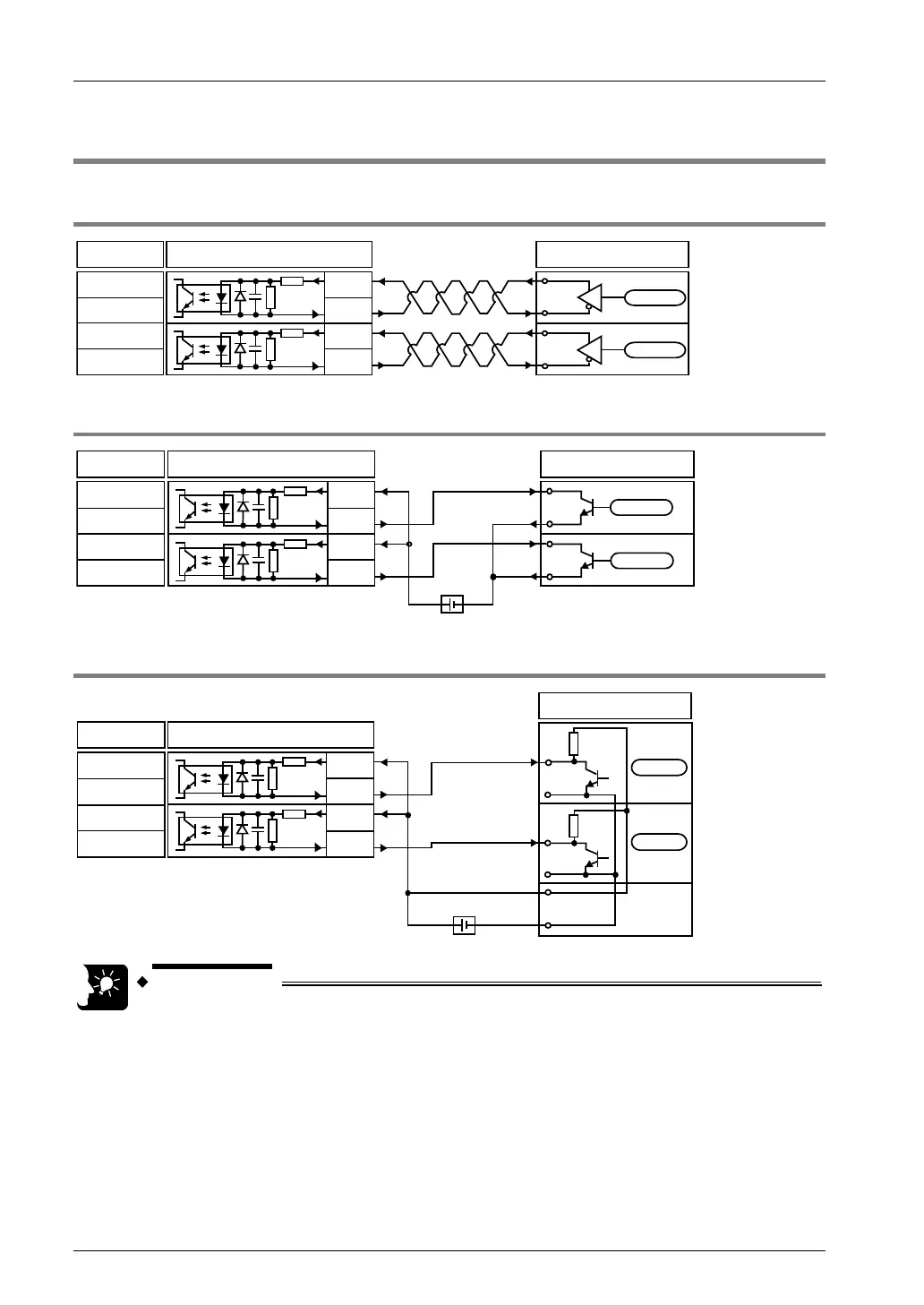
3.8 Connecting Pulse Input
3.8.1 Line Driver Type
Positioning unitConnection
Pulse input A (+)
Pulse input A (-)
Pulse input B (+)
Pulse input B (-)
560Ω
560Ω
Encoder, pulser
A phase
B phase
A8,A17
B8,B17
A9,A18
B9,B18
3.8.2 Transistor Open Collector Type
Connection Positioning unit
Pulse input B (-)
Pulse input A (-)
Pulse input A (+)
Pulse input B (+)
Power supply
Encoder, pulser
+5V DC GND
A phase
B phase
A8,A17
B8,B17
A9,A18
B9,B18
560Ω
560Ω
3.8.3 Transistor Resistance Pull-up Type
Connection Positioning unit
Pulse input A (+)
Pulse input A (-)
Pulse input B (+)
Pulse input B (-)
Power supply
Encoder, pulser
A phase
B phase
+5V DC GND
560Ω
560Ω
A8,A17
B8,B17
A9,A18
B9,B18
The pulser input operation and feedback pulse count of the unit uses the same pulse
input terminal. Therefore, select either one of them.
- The use of a twisted-pair cable is recommended.
- In the case of counting 2-phase inputs, such as encoder inputs, use a control code
and set the pulse input count to x4 or x2 for the prevention of counting errors.
Phone: 800.894.0412 - Fax: 888.723.4773 - Web: www.clrwtr.com - Email: info@clrwtr.com