Wiring
3-12
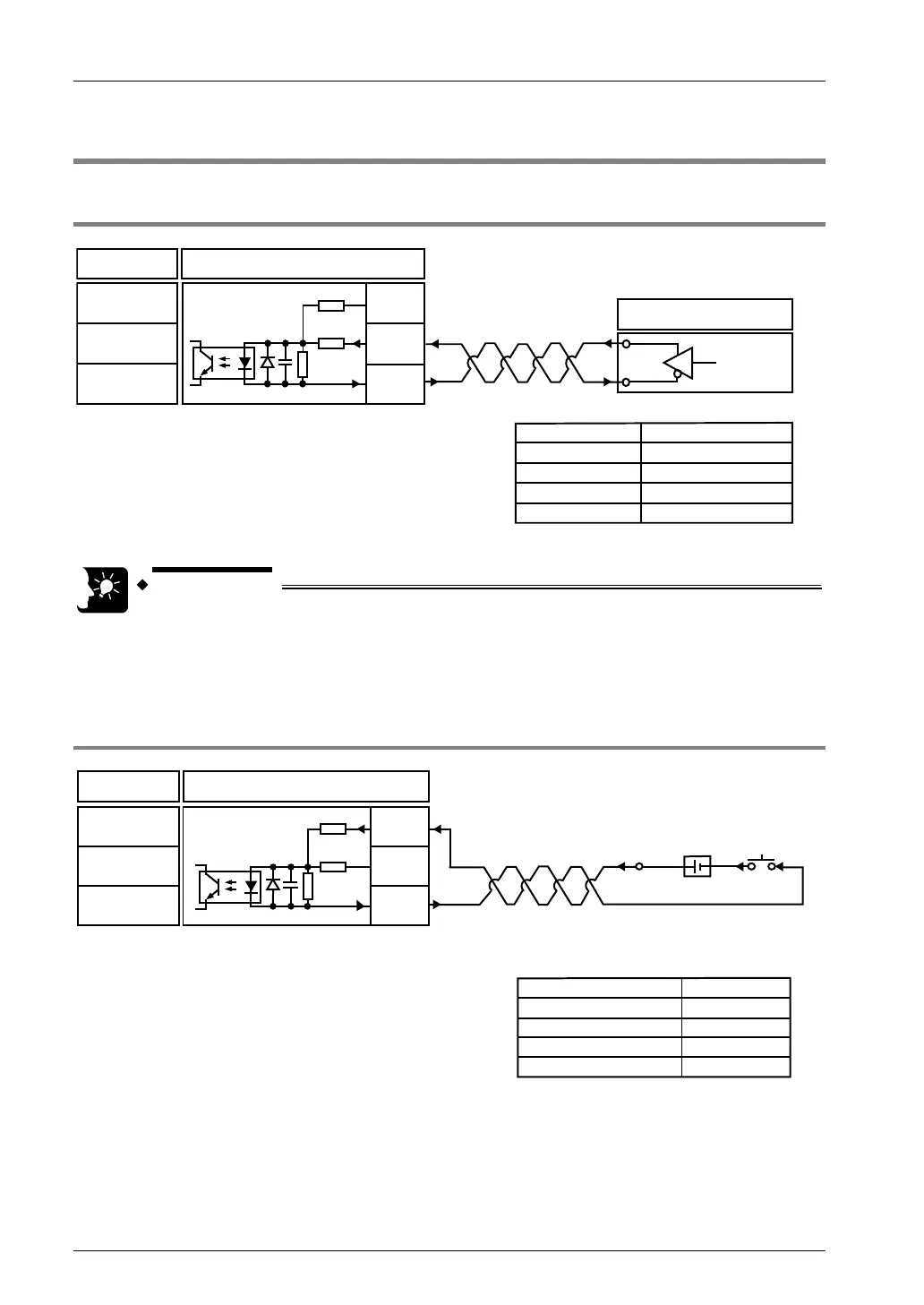
3.7 Connecting Home Input/Near Home Input Signal
3.7.1 Connecting Home Input (Connecting Motor Driver Z-phase Output)
Connection
Positioning unit
Home input
24V DC (+)
Home input
5V DC (+)
Home input
(-)
Motor driver
Z phase
signal
Input specifications (at 5V DC)
Input voltage range
Min. ON voltage/current
Max. OFF voltage/current
Input impedance
Min. input pulse width
3.5 to 5.25V DC
3V DC/4mA
1V DC/0.5mA
390Ω
100μs
A3,A12
A4,A13
B3,B12
3.9kΩ
560Ω
• The use of a twisted-pair cable is recommended to connect the output of
the positioning unit and the motor driver.
3.7.2 Connecting Home Input (Connecting External Switch Sensor)
Connection Positioning unit
Home input
24V DC (+)
Home input
5V DC (+)
Home input
(-)
Switch
Power supply
Input specifications (at 24V DC)
Input voltage range
Min. ON voltage/current
Max. OFF voltage/current
Input impedance
Min. input pulse width
24V DC
GND
21.6~26.4V DC
19.2V DC/5.5mA
2V DC/2mA
Approx. 3kΩ
100μs
A3,A12
A4,A13
B3,B12
3.9kΩ
560Ω
Phone: 800.894.0412 - Fax: 888.723.4773 - Web: www.clrwtr.com - Email: info@clrwtr.com