EasyManuals Logo

Panasonic FP7 User Manual

Panasonic FP7
275 pages
To Next Page IconTo Next Page
To Previous Page IconTo Previous Page
Page #38 background imageLoading...
Page #38 background image
Power On/Off and Check Items
4-2
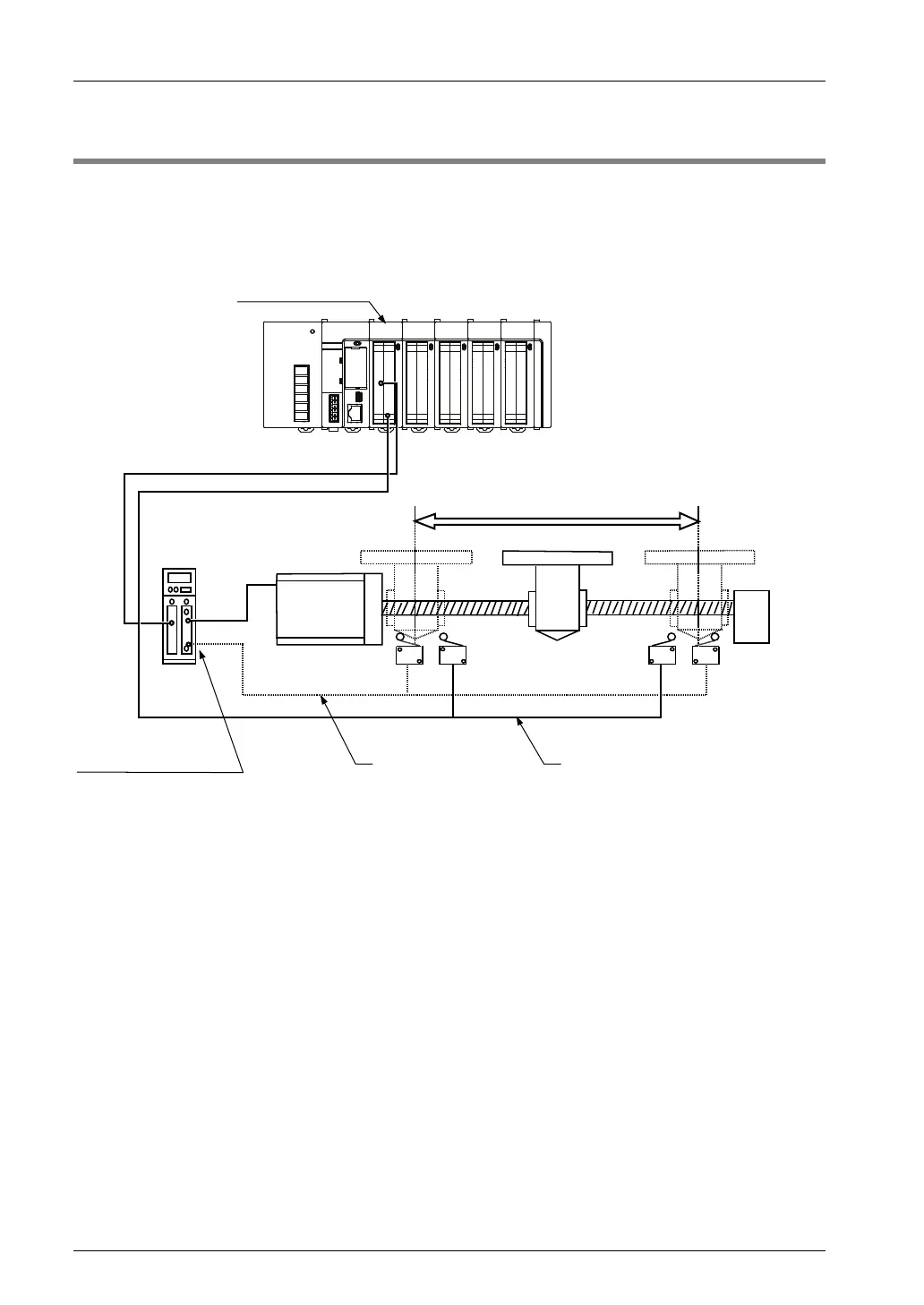
4.1 Safety Circuit Design
Example of a safety circuit
Installation of the over limit switch
Positioning unit
Motor driver
Motor
Driver upper and
lower limit input
External safety circuit
Input to positioning unit
CCW driving
inhibition switch
Over limit
switich
Over limit
switich
CW driving
inhibition
switch
Safety Circuit with Positioning Unit
Install over limit switches as shown above.
Connect the switch to the limit (+) input and limit (-) input of the positioning unit.
External safety circuit
Install the safety circuit recommended by the manufacturer of the motor being used.
Phone: 800.894.0412 - Fax: 888.723.4773 - Web: www.clrwtr.com - Email: info@clrwtr.com

Table of Contents

Questions and Answers:

Question and Answer IconNeed help?

Do you have a question about the Panasonic FP7 and is the answer not in the manual?

Panasonic FP7 Specifications

General IconGeneral
SeriesFP7
ManufacturerPanasonic
Input Voltage24 V DC
Data MemoryVaries by model
DimensionsVaries by model
WeightVaries by model
TypeProgrammable Logic Controller (PLC)
Output TypeRelay, Transistor
Number of InputsVaries by model
Number of OutputsVaries by model
Communication PortsEthernet, RS232C, RS485

Related product manuals