Automatic Operation (Positioning Control)
7-6
7.1.4 Setting and Operation of P-Point Control
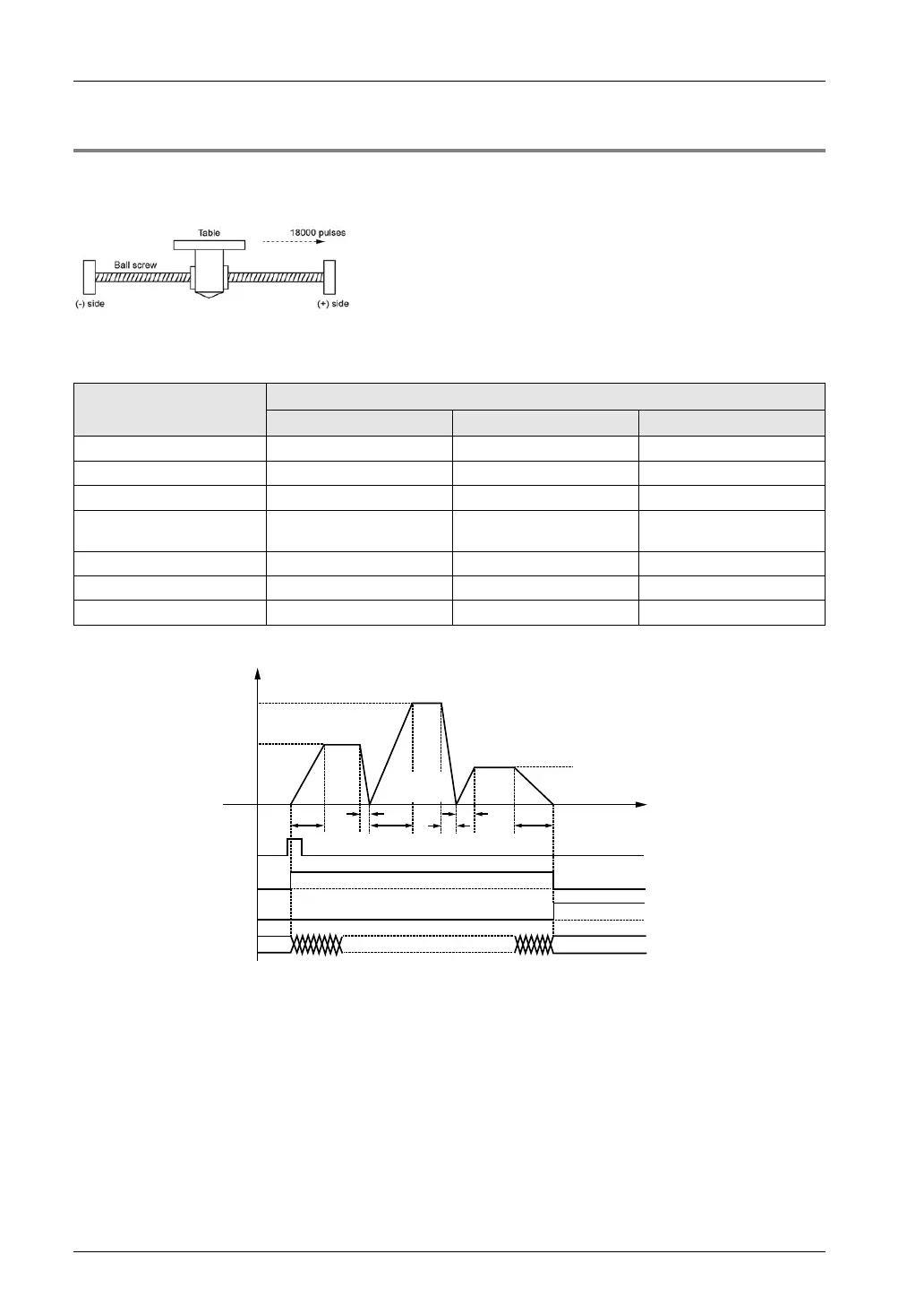
The example below is a case of single-axis control with the positioning unit installed in slot 1.
The movement amount setting uses an increment method in pulses.
Settings
Use the tool software to make positioning data and parameter settings. The unit is set to pulse.
Items Setting example
Table 1 Table 2 Table 3
Operation pattern C: Continuance point C: Continuance point E: End point
Control method I: Increment I: Increment I: Increment
X-axis movement amount 5000 pulses 10000 pulses 3000 pulses
Acceleration/deceleration
pattern
L: Linear L: Linear L: Linear
Acceleration time (ms) 100 ms 200 ms 30 ms
Deceleration time (ms) 10 ms 20 ms 150 ms
Target speed 10000 pps 20000 pps 5000 pps
Operation diagram
100
f [pps]
10000
20000
5000
200
10
20
30
150
t [ms]
3800020000
Table 1
5000
pulses
Table 2
10000
pulses
Table 3
3000
pulses
Positioning start contact Y110
Current value
Operation done flag X120
BUSY flag X118
Operation of each contact
• The BUSY flag (X118), which indicates that the motor is running, will turn ON when the
positioning control starts, and it will turn OFF when the operation completes.
• The operation done flag (X120), which indicates the completion of operation, will turn ON
when the current operation is completed, and it will be held until the next positioning control,
JOG operation, home return, or pulser operation starts. The flag will turn ON after the
positioning unit transmits a reference for the target position.
Phone: 800.894.0412 - Fax: 888.723.4773 - Web: www.clrwtr.com - Email: info@clrwtr.com