3.7 Connecting Home Input/Near Home Input Signal
3-13
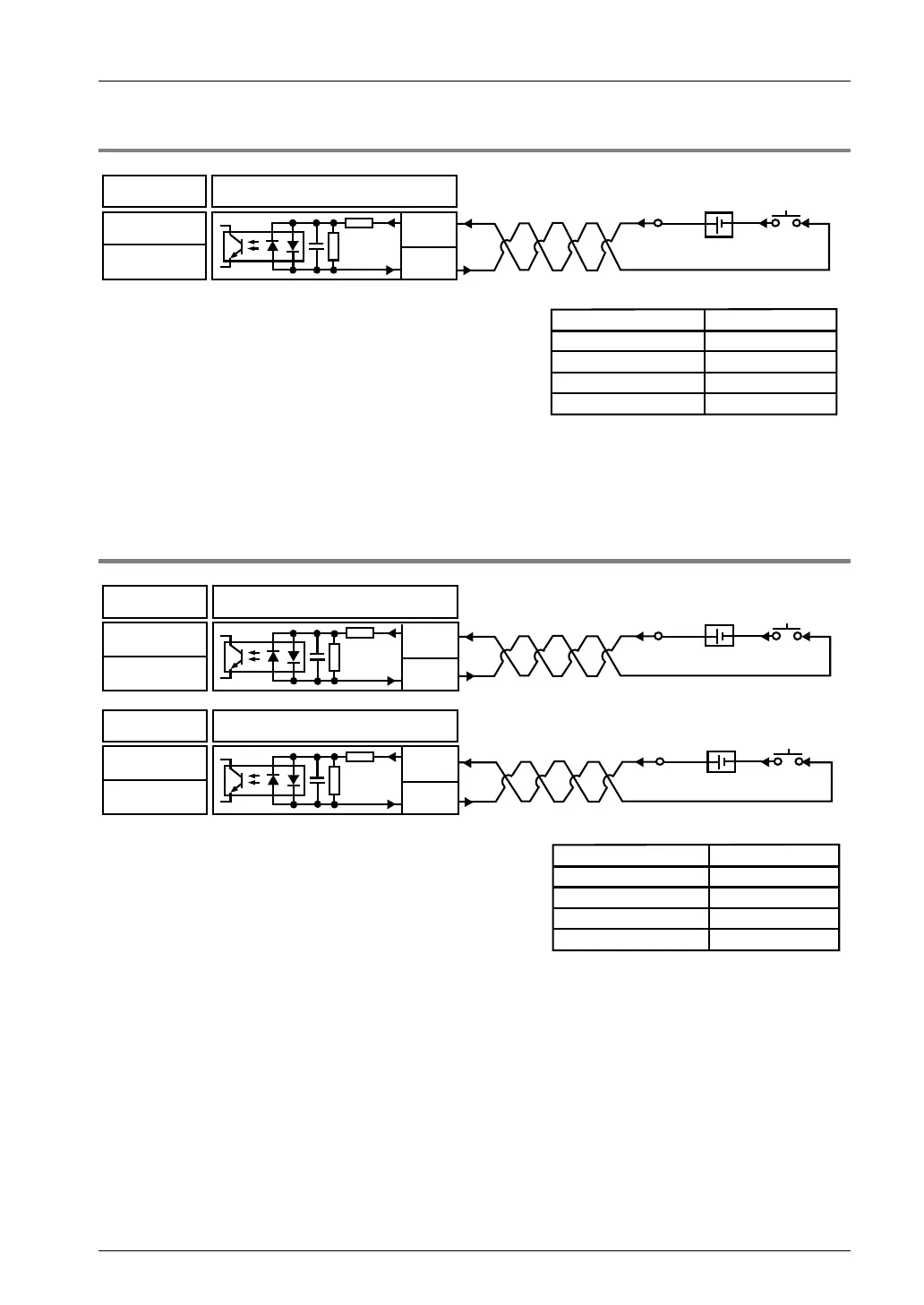
3.7.3 Connecting Near Home Input Signal
24V DC
GND
Connection
Positioning unit
Near home imput
Power supply
Switch
Input specifications
Input voltage range
Min. ON voltage/current
Max. OFF voltage/current
Input impedance
Min. input pulse width
500μs
Approx. 3.6kΩ
2V DC/1.5mA
19.2V DC/5.0mA
21.6 to 26.4V DC
COM
3.6kΩ
B4,B13
(COM)
A5,A14
(Note): B4 and B13 are common to near home input, limit (+) input, limit (-) input, and
positioning control start input (timing input).
3.7.4 Connecting Limit Input Signal
Input specifications
Input voltage range
Min. ON voltage/current
Max. OFF voltage/current
Input impedance
Min. input pulse width
Switch
Switch
Power supply
Power supply
Over limit
input (+)
Connection
Positioning unit
COM
B4,B13
(COM)
A6,A15
Over limit
input (-)
Connection
Positioning unit
COM
24V DC
24V DC
GND
GND
21.6~26.4V DC
19.2V DC/2.6mA
2V DC/1.5mA
500μs
Approx. 6.8kΩ
B4,B13
(COM)
B6,B15
6.8kΩ
6.8kΩ
(Note): B4 and B13 are common to near home input, limit (+) input, and limit (-) input.
Phone: 800.894.0412 - Fax: 888.723.4773 - Web: www.clrwtr.com - Email: info@clrwtr.com