7.2 Interpolation Control
7-15
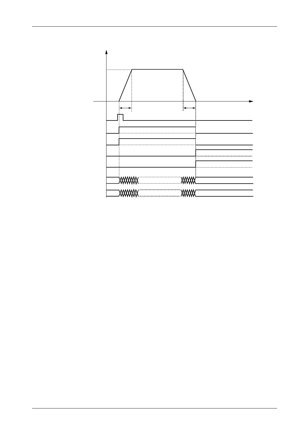
Operation diagram
100
100
f [pps]
10000
t [ms]
3000020000
1500010000
Composite speed
Positioning start contact of axis 1 Y110
Current value of axis 1
Current value of axis 2
Operation done flag of axis 1 X120
Operation done flag of axis 2 X121
BUSY flag of axis 1 X118
BUSY flag of axis 2 X119
Operation of each contact
• The 1st axis and 2nd axis BUSY flags (X118 and X119) indicating the state that a motor is
running will turn ON when the positioning control starts, and they will turn OFF when the
operation completes.
• The 1st axis and 2nd axis operation done flags (X120 and X121) indicating the state that an
operation completed will turn ON when the JOG operation is completed, and they will be
held until the next positioning control, JOG operation, home return, or pulser operation starts.
Programming Precautions
• To start the interpolation control, turn ON the positioning start contact of the axis with the
smallest number in the same group.
• The values of the X-axis auxiliary point and Y-axis auxiliary point are invalid for the linear
interpolation.
• In the case of specifying long axis speed, the composite speed will be faster than the long
axis speed.
• If any value such as a movement amount, acceleration time, deceleration time or target
speed is out of the specified range, a set value error will occur when the positioning control
starts.
• The start contact and flag number varies depending on the number of axes and the
installation position of the unit.
• The specified slot number varies depending on the installation position of the unit.
Phone: 800.894.0412 - Fax: 888.723.4773 - Web: www.clrwtr.com - Email: info@clrwtr.com