Previous Page Table of Contents Section Contents
Back
Index Next Page
LIFEPAK 20/20e Defibrillator/Monitor Replacement Procedures
Front Case (continued)
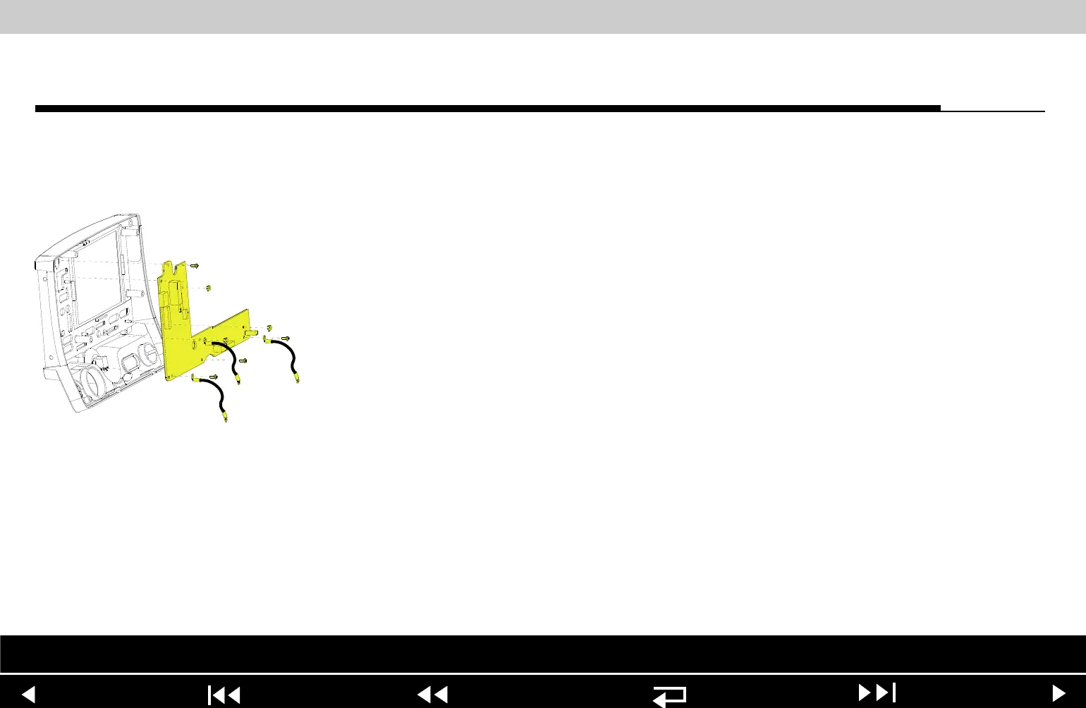
A05 User Interface (UI)
PCB Removal
Note: The following assemblies must be removed before beginning this
disassembly:
– Top case
– Front case
– Active display assembly
To remove the A05 UI PCB:
1. Disconnect the W18 UI Flex Cable from the A05 UI PCB at J31.
2. Remove the Speed Dial connector from the A05 UI PCB at J32.
3. Remove and discard the three 4-40 0.312 screws (173) from the bottom
edge of the A05 UI PCB. Remove the two grounding harnesses (221)
attached to the left and right corner screws.
Note: Replace any broken or frayed grounding harnesses.
Note: If replacing the A05 UI PCB, transfer the grounding harnesses to the
new PCB.
Parts List Interconnect Front Case View Rear View Main Assemblies
9-52