Previous Page Table of Contents Section Contents
Back
Index Next Page
LIFEPAK 20/20e Defibrillator/Monitor Replacement Procedures
Boardstack (continued)
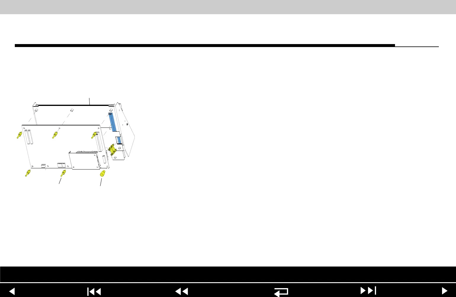
A01 System PCB
Removal
Note: Remove the following assemblies before beginning this disassembly:
– Top case
– Front case
– Boardstack assembly
– A02 Patient Parameter PCB (and A06 OEM/SpO2 assembly, if
applicable)
To remove the A01 System PCB:
1. Remove the PCB shield (127).
2. Remove and discard the five threaded standoffs (129) from the A01 System
PCB.
3. Remove the round, snap-in standoff (265) from the A01 System PCB.
4. Remove the A01 System PCB from the PCB support bracket (139).
5. Locate the 8-pin stack connector (135) (connects the A01 System PCB J03
with the A04 Therapy PCB at J15), and safeguard it for reuse.
Note: The 8-pin stack connector may remain connected to the A04 Therapy
PCB or the A01 System PCB, or it may fall out completely when the
A01 System PCB is removed. Be sure to account for it immediately.
Parts Lists Interconnect System View Therapy View Main Assemblies
9-98