Previous Page Table of Contents Section Contents
Back
Index Next Page
LIFEPAK 20/20e Defibrillator/Monitor Replacement Procedures
Boardstack (continued)
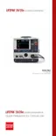
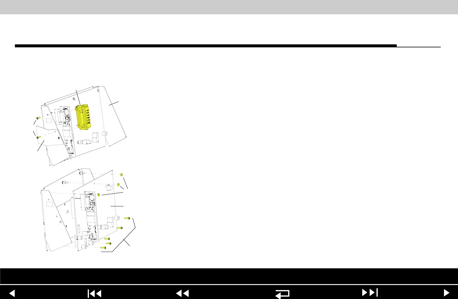
A04 Therapy PCB
Removal
Note: Remove the following assemblies before beginning this disassembly:
– Top case
– Front case
– Boardstack assembly
To remove the A04 Therapy PCB:
1. Remove and discard the two 4-40 0.312 screws (173) connecting the
inductive resistor assembly (A14) to the PCB support bracket (139).
2. Remove the inductive resistor assembly (A14).
3. Remove and discard the five 4-40 0.500 screws (185) located inside the
five insulated standoffs.
Note: The standoffs should remain with the A04 Therapy PCB.
4. Remove the three 4-40 nuts (161) from the metal standoffs along the top
edge of the A04 Therapy PCB (see illustration B at left).
5. Remove the A04 Therapy PCB from the PCB support bracket (139).
6. Locate the 8-pin stack connector (135) (connecting the A01 System PCB at
J3 with the A04 Therapy PCB at J15) and safeguard it for reuse.
A
B
173
A14
139
161
185
A04
(x5)
(x3)
278
Parts Lists Interconnect System View Therapy View Main Assemblies
9-102