Previous Page Table of Contents Section Contents
Back
Index Next Page
LIFEPAK 20/20e Defibrillator/Monitor Replacement Procedures
Boardstack (continued)
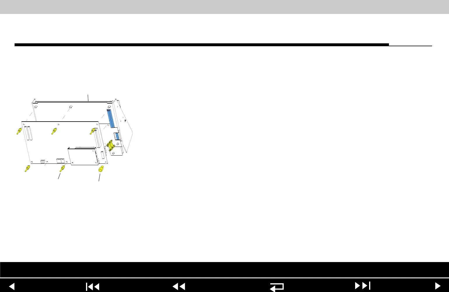
A01 System PCB
Installation
To install the A01 System PCB:
1. If you are replacing the A01 System PCB, ensure that the plastic standoff
(149) is correctly positioned, large end up, on the A01 System PCB.
2. Insert the 8-pin stack connector (135) into the A04 Therapy PCB at J15.
3. Carefully position the A01 System PCB over the PCB support bracket (139),
and slide it down the support bracket standoffs. As the A01 System PCB
slides down, ensure that the support bracket standoffs and the pins on the
8-pin and 60-pin stack connectors seat with their connectors evenly.
4. Install five new threaded standoffs (129), long end up, into the support
bracket.
Note: Do not install a screw in the insulated standoff in the lower right
corner at this time.
5. Replace the coin battery if needed.
6. Install the PCB shield (127) by sliding it down the five threaded standoffs on
the A01 System PCB.
Parts Lists Interconnect System View Therapy View Main Assemblies
9-99