Previous Page Table of Contents Section Contents
Back
Index Next Page
LIFEPAK 20/20e Defibrillator/Monitor Replacement Procedures
Front Case (continued)
A05 User Interface (UI)
PCB Removal
(continued)
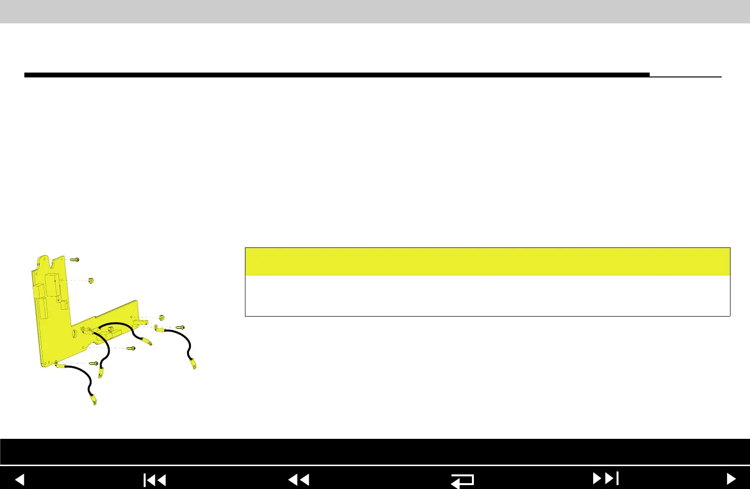
4. Remove and discard the 4-40 0.312 screw (173) from the top left corner of
the A05 UI PCB.
5. Remove the three 4-40 nuts (161) from the A05 UI PCB. Remove the two
grounding harnesses attached to the center nut.
6. Remove the A05 UI PCB from the front case.
A05 User Interface (UI)
PCB Installation
To install the A05 UI PCB:
1. Position the A05 UI PCB onto the front case.
2. Insert the grounding harness (246) from the W04 Speed Dial Assembly, and
a second grounding harness (219) to the lower center stud, and install the
three 4-40 nuts (161) onto the A05 UI PCB; torque nuts to 6.8 in-lb. Refer to
Grounding Harness Orientation for grounding harness placement.
CAUTION
Possible component damage. The grounding harnesses must be installed at
precise angles to avoid damaging device components.
Parts List Interconnect Front Case View Rear View Main Assemblies
9-53