Because RFL™ and Hubbell® have a policy of continuous product improvement, we reserve the right to change designs and specifications without notice.
4.3 SETTING JUMPERS ON THE CM4 COMMON MODULE
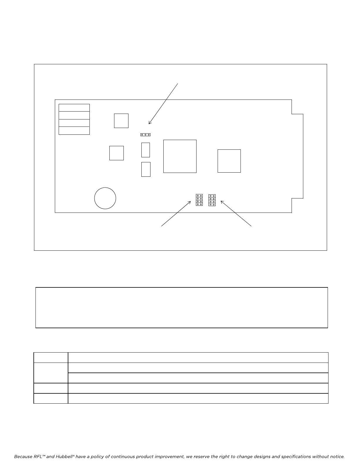
TEST J8 RUN
J3 J4
T1 422
J8
J3
Figure 4-1. Location of jumpers on the CM4 common module.
The CM4 Common Module has three sets of jumpers that must be set for proper system operation.
These are J8, J3 and J4. Refer to Table 4-1 for information on how to set these jumpers.
NOTE
External timing of the CM4 in an IMUX 2000 M-DACS is not required. External timing is
done through the DASC module via the communications I/O (MA-235).
Table 4-1. Setting CM4 jumpers
Jumper Function
J8 Place jumper J8 in RUN position for normal system operation.
Place jumper J8 in TEST position for factory testing only.
J3 Place all four J3 jumpers in T1 position to select external timing input in T1 format.
J4 Place all four J4 jumpers in 422 position to select external timing input in RS422 format.
Note: All other jumpers on the CM4 are used for FACTORY TESTING only.
M-DACS-T1 RFL Electronics Inc.
July 18, 2008 4-2 (973) 334-3100