Because RFL™ and Hubbell® have a policy of continuous product improvement, we reserve the right to change designs and specifications without notice.
8.2.7 USING T1 TEST EQUIPMENT TO PERFORM OUT-OF-SERVICE
TESTS
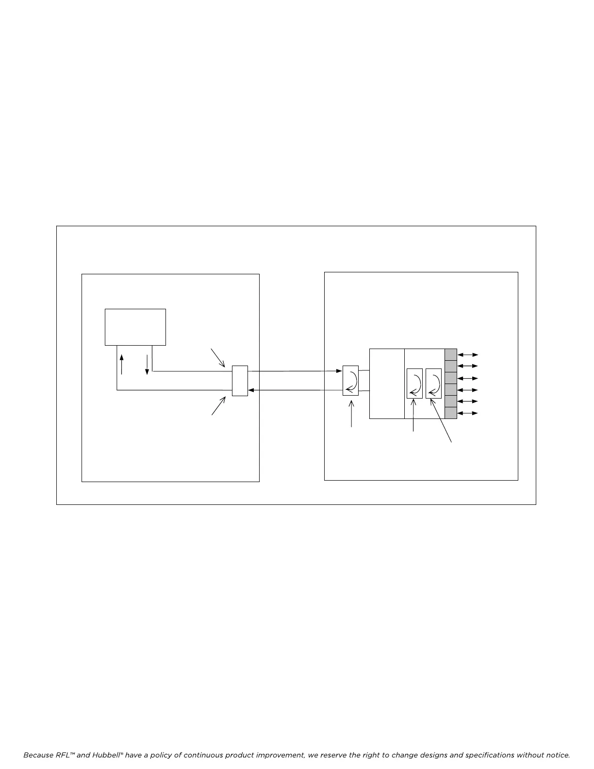
Use T1 test equipment to test T1 facilities on an out-of-service basis, as illustrated in Figure 8-4. For
compatibility with all carrier networks, we recommend that you use test equipment that is capable of
generating framed T1 signals.
In a carrier central office, T1 out-of-service testing generally takes place at a DSX-1 bay. At a
customer site, testing can be done using the test jacks at the T1 Channel Service Unit (CSU).
T1
CIRCUIT
RECEIVE OUT
JACK
TRANSMIT IN
JACK
LOCATION 1
MANUAL
LOOPBACK
(PATCHCORD)
CM4
D/I-A or B
VOICE
AND
DATA
CIRCUITS
CM4
LINE
LOOPBACK
CM4
PAYLOAD
LOOPBACK
DACS
Module
DSX-1
LOCATION 2
DSX-1
T1 TEST SET
IN
OUT
Figure 8-4. Out-of-service testing of a T1 circuit
M-DACS-T1 RFL Electronics Inc.
October 25, 2004 8-8 (973) 334-3100