Because RFL™ and Hubbell® have a policy of continuous product improvement, we reserve the right to change designs and specifications without notice.
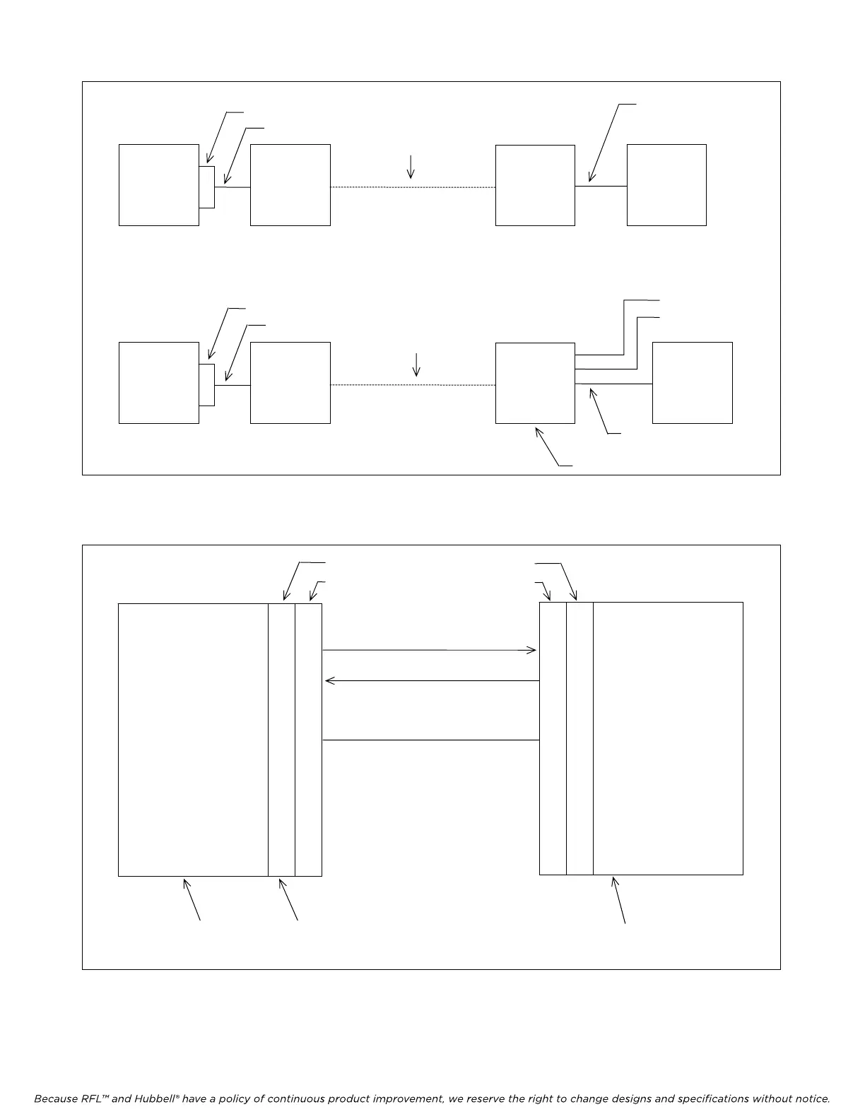
Figure 5-3. PC connected to a node from a remote location
PUBLIC OR
PRIVATE
PHONE LINE
PC
MODEM
MODEM
NODE
COM1 or COM2
PC
MODEM
RFL 9660
DIGITAL
SWITCH
NODE
PUBLIC OR
PRIVATE
PHO
NE LINE
TO OTHER
DEVICES
COM1 or COM2
PORT 1
PORT 2
PORT 3
SUBSTATION SWITCH
a. Using modems only.
b. Using modem and substation switch.
RS232 cable
RS232 cable
Null modem cable
may be required
Null modem cable
is required
NC
XMIT DATA OUTPUT
REC DATA INPUT
NC
RS-23
2 GROUND
NC
NC
NC
NC
1
3
2
4
5
6
7
8
9
1
3
2
4
5
6
7
8
9
1
3
2
4
5
6
7
8
9
1
3
2
4
5
6
7
8
9
NC
REC DATA INPUT
XMIT DATA OUTPUT
NC
RS-232 GROUND
NC
NC
NC
NC
MALE
FEMALE
MALE
FEMALE
PC
COM1
PORT
MA-235
Figure 5-4. Construction of a typical RS-232 cable between the PC and an MA-235
M-DACS-T1 RFL Electronics Inc.
February 28, 2006 5-6 (973) 334-3100