Because RFL™ and Hubbell® have a policy of continuous product improvement, we reserve the right to change designs and specifications without notice.
5.5.3.8 CONNECTING LINES TO NODES
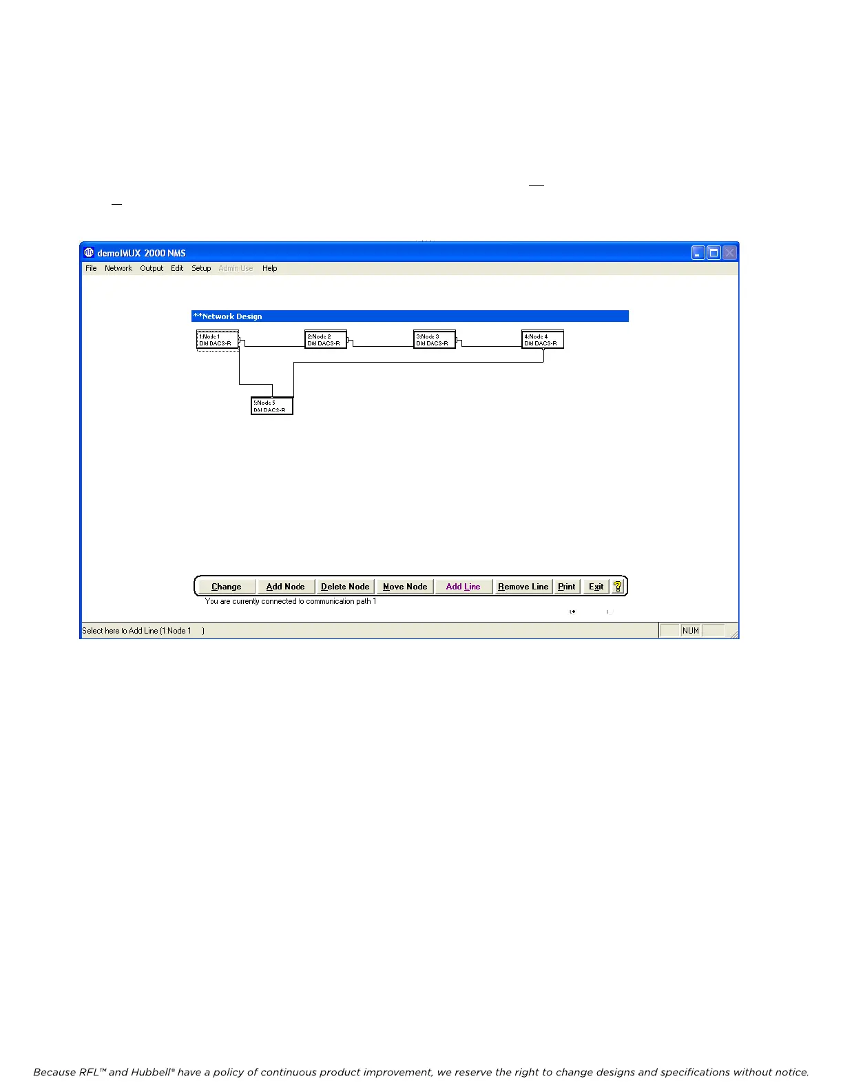
After the entire network has been configured return to the Network View window shown in Figure 5-
15. Connect the lines between nodes in accordance with Figure 5-9. To make the Network View more
readable the nodes can be moved to different locations by using the Move Node button. Then use the
Add L
ine button to add connecting lines between nodes. When you are finished connecting lines to
nodes, your Network View window should be similar to the one shown below in Figure 5-33.
Figure 5-33. Network View window after connecting lines to nodes
M-DACS-T1 RFL Electronics Inc.
February 28, 2006 5-50 (973) 334-3100