Because RFL™ and Hubbell® have a policy of continuous product improvement, we reserve the right to change designs and specifications without notice.
DROP/INSERT
MULTIPLEXER
4
2 3 1
M-DACS B
2
3
1
6
5
1
3
2
4
56
M-DACS C
M-DACS D
5
6
1
3
2
4
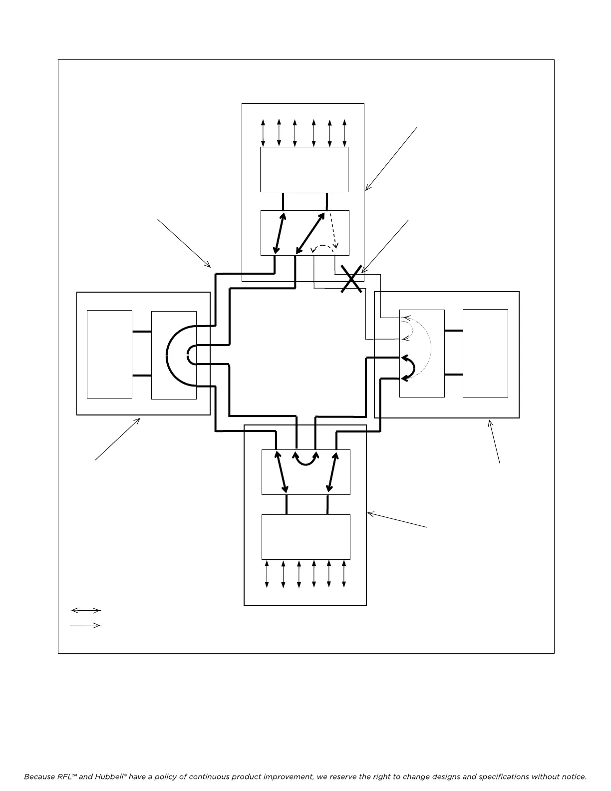
“
” represents a break in any
one of the primary path fiber
optic cables. Only the maps for
M-DACS A and M-DACS B are
effected. The DACS Map Select
Criteria which was programmed
by the user causes M-DACS A
to switch to map 1 and M-DACS
B to switch to map 4.
Each line represents 2 fiber optic
cables, one for transmit and one
for receive.
When a break occurs as shown,
M-DACS D stays in map 0
since it has no knowledge of the
break. Refer to M-DACS D,
Map 0 (Table 1-6)
When a break occurs as
shown, M-DACS C stays in
map 0 since it has no
knowledge of the break
.
Refer to M-DACS C, Map 0
(Table 1-5)
= bi-directional communication
= mono-directional
Refer to M-DACS A,
Map 1 (Table 1-2)
Refer to M-DACS B,
Map 4 (Table 1-4)
CH1
CH2
CH3
CH4
CH5 CH6
7
8
7
8
7 8
CH1 CH2 CH3 CH4 CH5 CH6
DROP/INSERT
MULTIPLEXER
5
6
M-DACS A
DROP/
INSERT
MULTI-
PLEXER
DROP/
INSERT
MULTI-
PLEXER
4 Fiber Ring
Figure 2-11. M-DACS fiber ring configuration after a failure (sample configuration)
M-DACS-T1 RFL Electronics Inc.
October 16, 2012 2-15 (973) 334-3100