Because RFL™ and Hubbell® have a policy of continuous product improvement, we reserve the right to change designs and specifications without notice.
4.17 RESET-CHART PROCEDURE FOR CM4 MODULE
1. This procedure will reset the “channel configuration table” on the CM4 module.
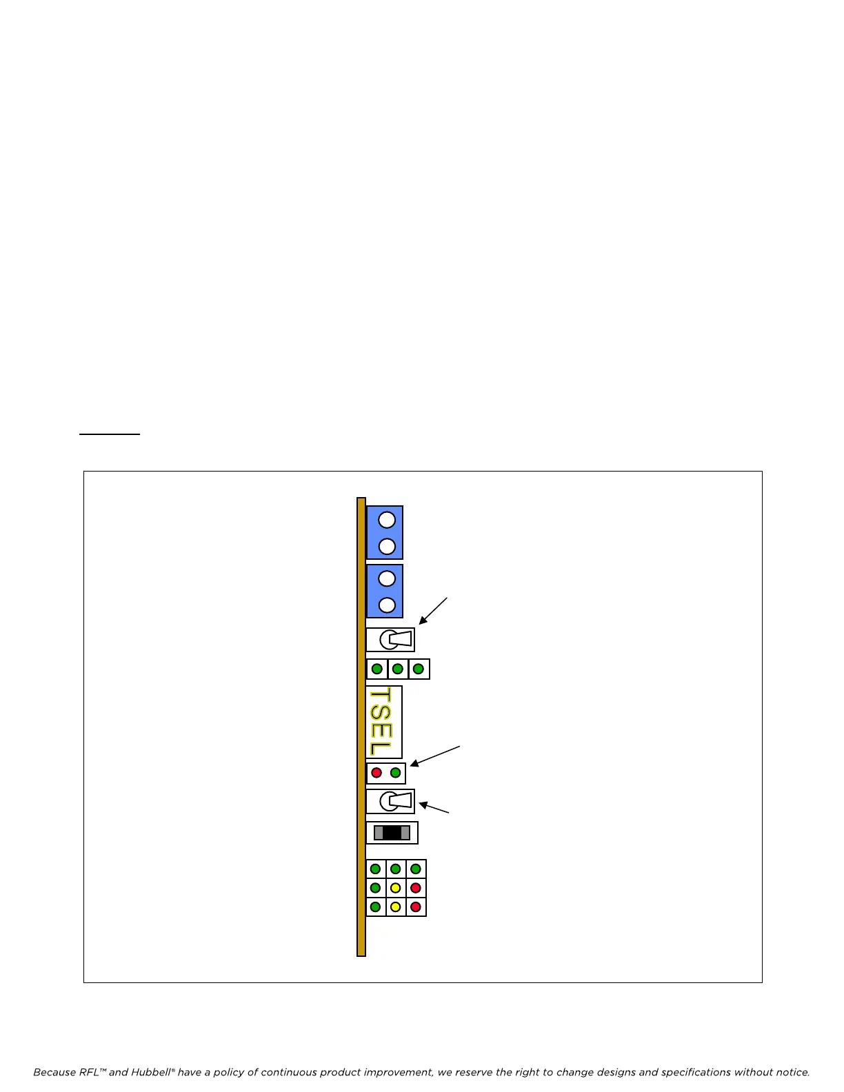
2. Toggle the GROUP switch toward the board (left) until the display shows Function Group
“RVU1”.
3. Toggle the GROUP switch toward the board (left) once and hold it. At the same time toggle
SET/NEXT switch away from the board (right) in order to get into the Supplementary Group.
4. The first Function Group in the Supplementary Group is “FTIM”.
5. Toggle the SET/NEXT switch toward the board (left) until the display shows Function “RCHT”
(Reset Chart).
6. At this point ON/OFF LED should be RED.
7. Toggle the SET/NEXT switch TWICE away from the board (right).
Caution: Performing this procedure will delete configuration of all channel modules and may cause
undesired operation of the system.
GROUP
switch
M-DACS-T1 RFL Electronics Inc.
Figure 4-6. View of CM4 showing switches used in Reset-Chart procedure
SET/NEXT switch
ON/OFF
LED
July 18, 2008 4-29 (973) 334-3100