Because RFL™ and Hubbell® have a policy of continuous product improvement, we reserve the right to change designs and specifications without notice.
2.4.3 INDICATORS AND TOGGLE SWITCHES USED TO DISPLAY AND SET
T1 COMMON MODULE FUNCTIONS
Table 2-16 describes the controls and indicators which display and set CM4 setup and status functions.
Table 2-17 lists CM4 functions, organized by group. Table 2-18 lists CM4 Supplementary Functions,
organized by group. Figure 2-20 is an overview of all CM4 groups and functions. (Section 6 of this
manual contains detailed instructions on using CM4 functions.)
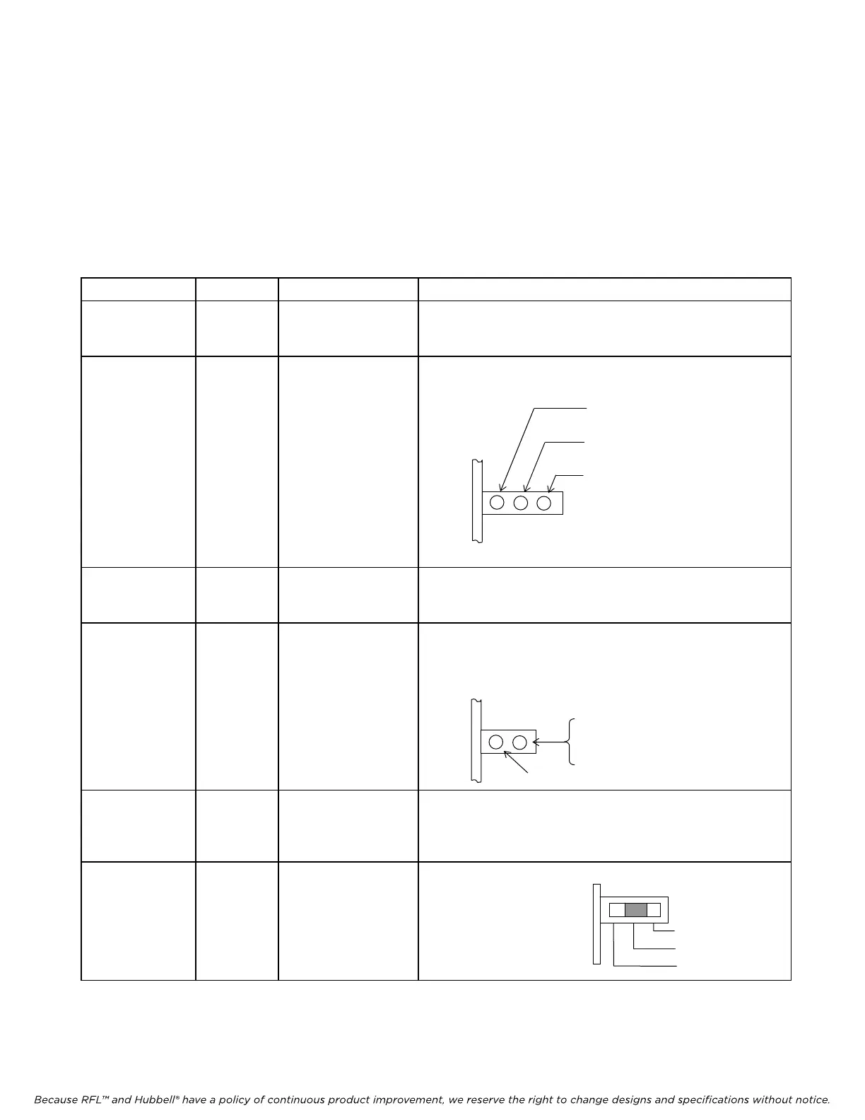
Table 2-15. Indicators and toggle switches used to display and set T1 Common Module functions
Item (Fig. 2-27) Module Label Description
10 CM4 GROUP
This two-position momentary contact toggle switch selects the
CM4 f
unction group (See Paragraph 5.5 for information on
how to use the Group Switch.)
11
(NOT USE
D
IN M-DACS)
(ALL
LEDS
SHOULD BE
ON)
CM4
CONFIG
BRD OK
ACTIVE
Redundant Mode Activity indicator consisting of three green
LEDs
M-DACS-T1 RFL Electronics Inc.
12 CM4
ACTIVE: When lit, this CM4 is the
active board.
BRD OK: When lit, this CM4
module is
functional.
CONFIG: When lit, this CM4 is
fully configured.
FUNCTION
This four-character alphanumeric display lists CM4 function
grou
p names and individual function names. (See Tables 2-8
and 2-9 for more information)
13 CM4 ON/OFF
This bi-color LED indicator shows the status of the currently-
disp
layed function. The LED will light GREEN if the
function is ON or has been set. The LED will light RED if
the function is OFF or has not been set.
ON (green)
OFF
red
Not used
14 CM4 SET/NEXT
This switch is a three position, center-off, momentary contact
toggle switch
. This toggle switch displays and sets CM4
function groups. (See Paragraph 5.5 for information on how
to use the Set/Next Switch.)
15
(NOT USE
D
IN M-DACS)
CM4 - - - 3-position Redundancy Control slide switch
Up (Right) = Main
Center (Center) = Auto
Down (Left) = Standby
NOTE: When you are facing the front of the multiplexer, the "up" position of each toggle switch or slide switch is to the
right, and its "down" position is to the left.
Main
Auto
Standb
October 16, 2012 2-53 (973) 334-3100