Because RFL™ and Hubbell® have a policy of continuous product improvement, we reserve the right to change designs and specifications without notice.
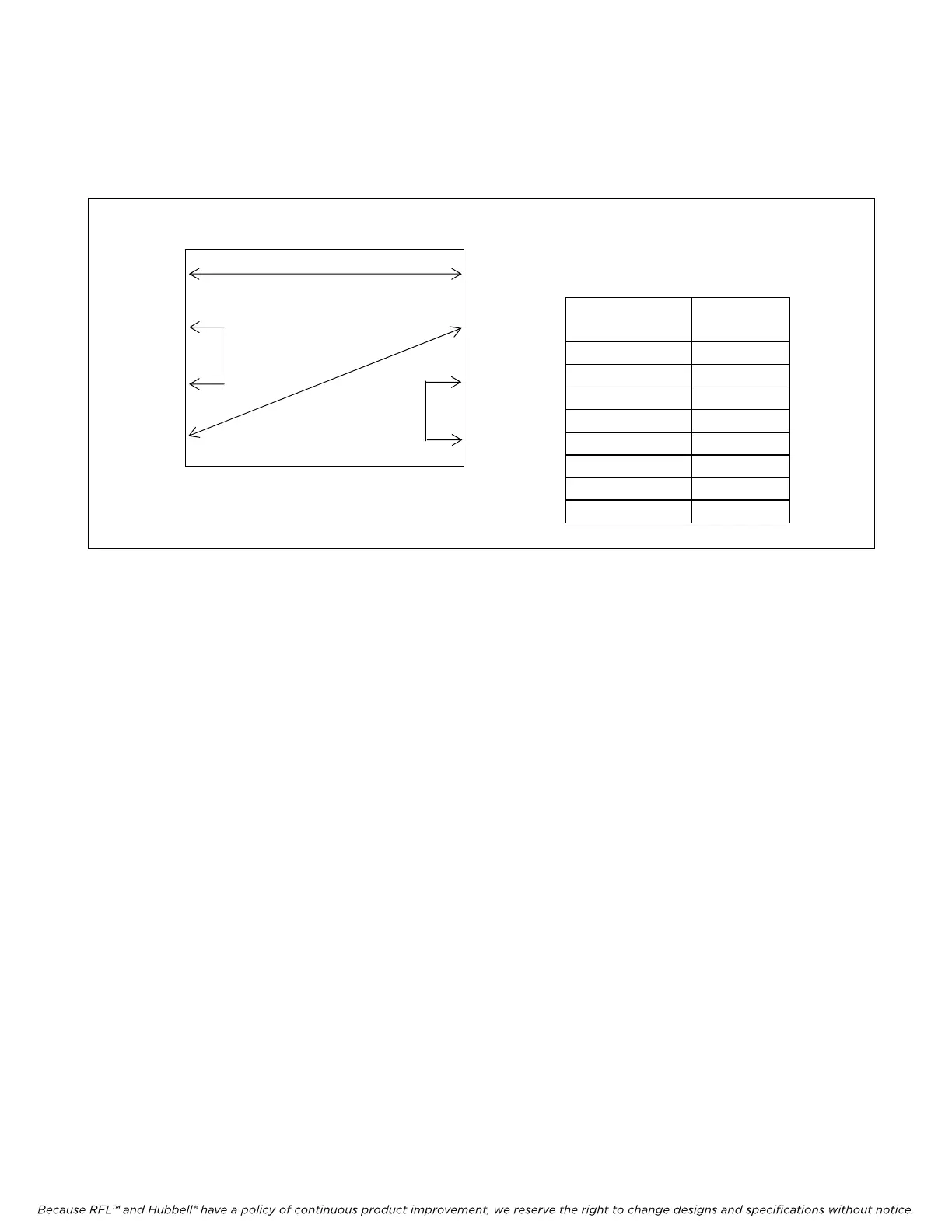
The next step is to select the FDL/Line Route for “Map 0”. Program the routing of the FDL/Line Route
signal for “Port 1 Tx” through “Port 8 Tx” as shown in the figure and table below. The number
entered for each port indicates which Rx Port to take the FDL data from.
M-DACS-T1 RFL Electronics Inc.
FDL/Line
Route
Map 0
Port 1 TX 5
Port 2 TX 3
Port 3 TX 2
Port 4 TX 6
Port 5 TX 1
Port 6 TX 4
Port 7 TX 8
Port 8 TX 7
Port 1
Port 5
Port 2
Port 6
Port 3
Figure 5-23. Typical FDL signal routing for map 0
Then program the FDL/Line Route for “Map 1” through “Map 7” in a similar way depending on your
system requirements. After all FDL/Line Routes have been programmed click on “Map Select
Criteria”. This will bring you to the Map Select Criteria window as shown in Figure 5-24.
February 28, 2006 5-36 (973) 334-3100