Because RFL™ and Hubbell® have a policy of continuous product improvement, we reserve the right to change designs and specifications without notice.
5.5.3.7.1 DACS MODULE CONFIGURATION WINDOW
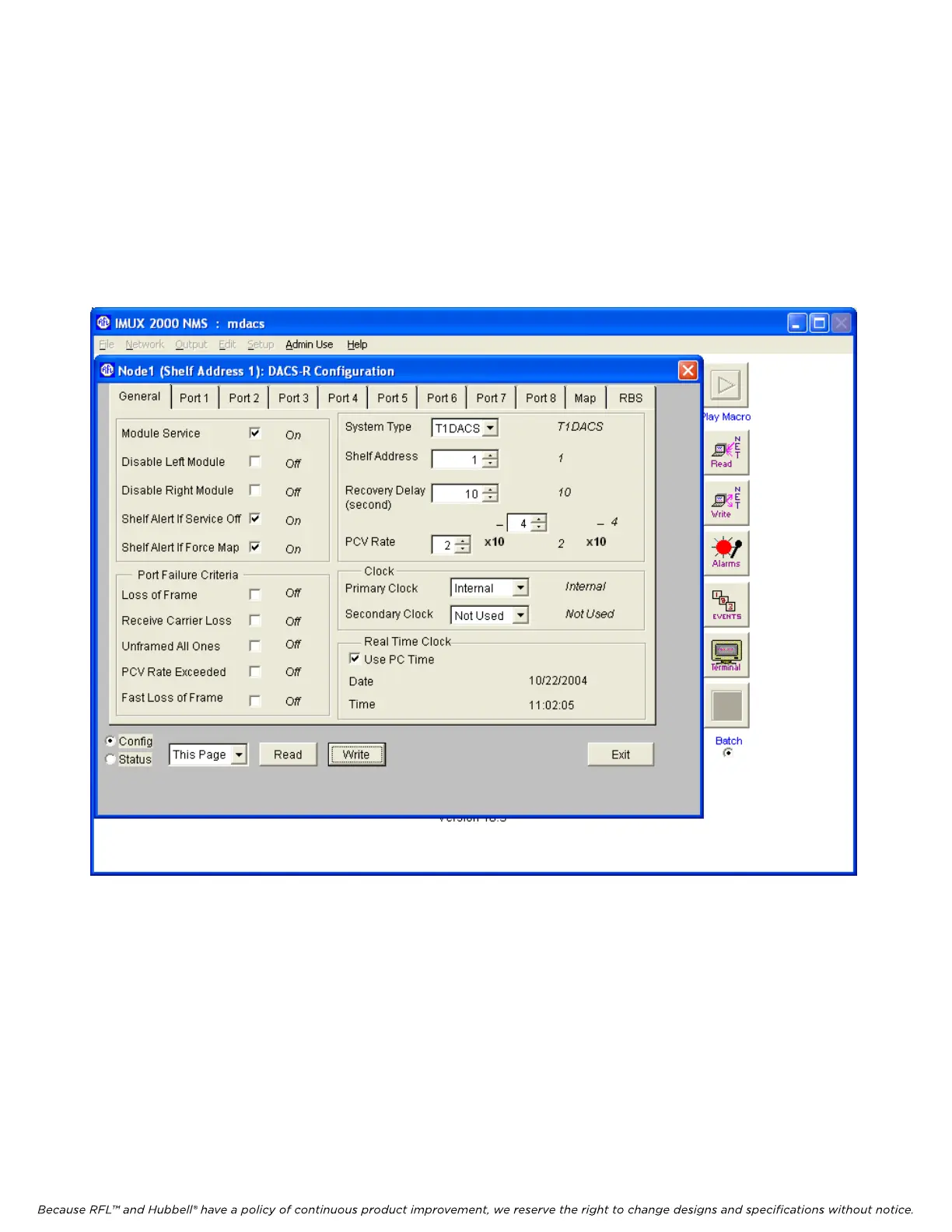
The DACS Module General Configurations window for Node 1 is shown in Figure 5-17. This is where
the user can view or change the DACS module general configuration parameters. The user can change
parameters by making selections in the control boxes. The actual values appear immediately to the
right of the control boxes. This window has eleven top-level pages selectable by the tabs at the top of
the window as follows: General, Port 1 to Port 8, Map and RBS (Robbed Bit Signaling). The following
discussion covers the settings on the “General” page.
Figure 5-17. DACS Module Configuration Window
M-DACS-T1 RFL Electronics Inc.
February 28, 2006 5-25 (973) 334-3100