Because RFL™ and Hubbell® have a policy of continuous product improvement, we reserve the right to change designs and specifications without notice.
2.6 MULTIPLEXER, SETUP JUMPERS AND DIP SWITCHES
Setup jumpers are located on some Module Adapters, OIA Optical Interface Adapters and on the CM4
Common Module. Table 2-28 briefly describes the use of the setup jumpers. A complete discussion of
the location and function of each setup jumper appears in Section 5 of this manual.
Table 2-25. Setup jumpers and DIP switches
Module Labels Description
MA-235
NA NA
CM4 J8 Used to select RUN or TEST modes. For normal system operation, jumper
should be in RUN position. TEST position is for factory use only.
J3 an
d J4
(NOT USED
IN M-DACS)
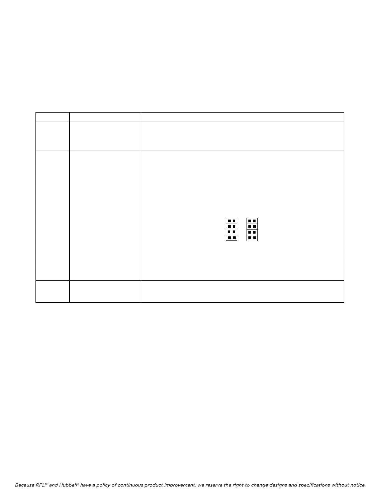
Used to select T1
or RS422 external timing input formats as follows:
Fill all four J3 positions to select external timing input in T1 format as
sho
wn bel
ow.
Fill all four J4 positions to select external timing input in RS422 format as
shown bel
ow.
M-DACS-T1 RFL Electr
onics Inc.
Note: Th
e external timing output is always in 422 format.
All other jumpers are for factory use only.
J3 J4
T1
422
OIAs NA NA
October 16, 2012 2-63 (973) 334-3100