Because RFL™ and Hubbell® have a policy of continuous product improvement, we reserve the right to change designs and specifications without notice.
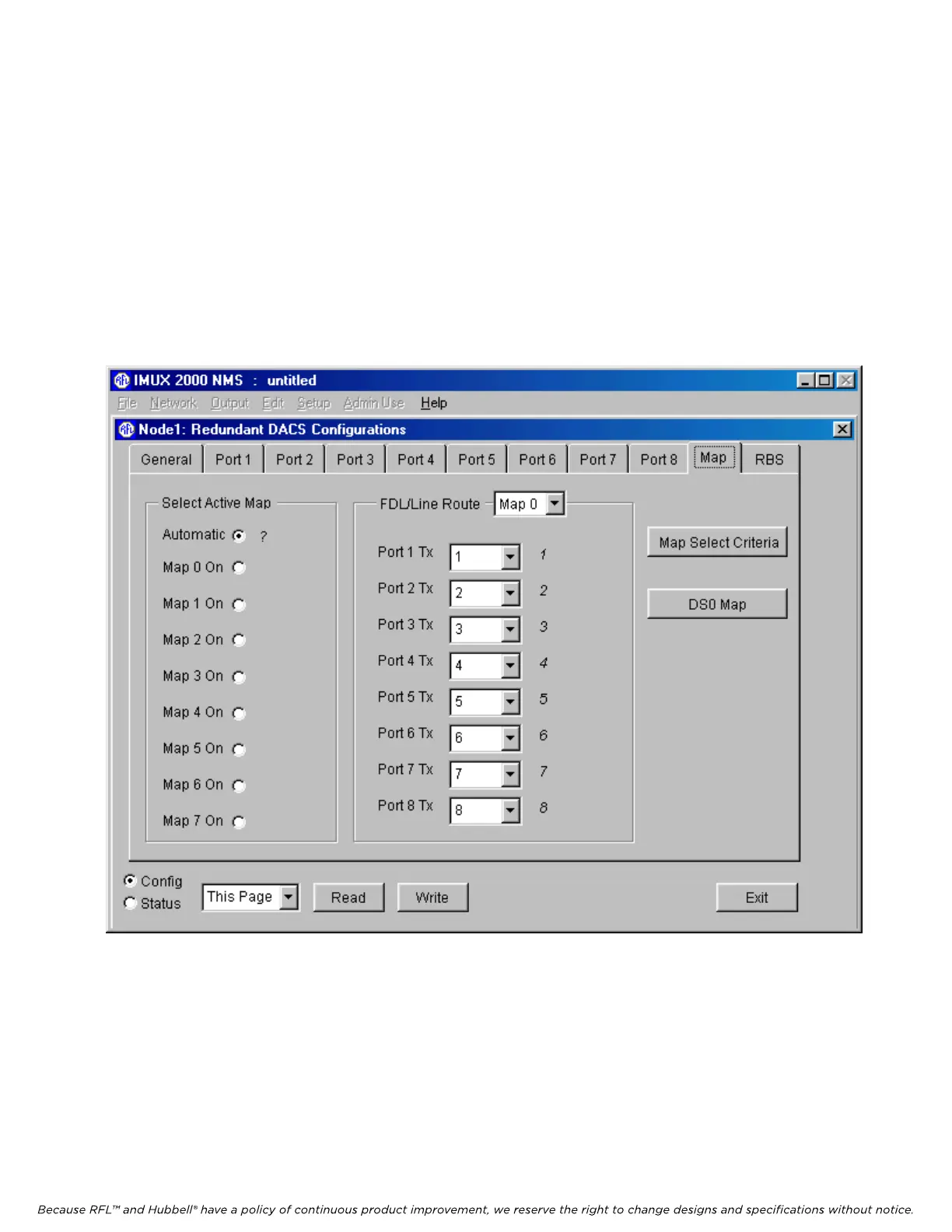
5.5.3.7.3 DACS MAP WINDOW
When the DACS module is operating normally it is in Map 0. The first time a DACS module is
powered up, all maps (Map 0 through Map 7) have random information in them and must be
programmed by the user. To do this, click on the “Map” tab. This will bring you to the DACS Map
window shown in Figure 5-22
In the “Select Active Map” box click on the “Automatic” radio button. This will allow the DACS
module to switch to an alternate map automatically upon a failure. This is the normal setting. The
“Map 1 On” through “Map 7 On” radio buttons will allow the user to force the DACS module to
switch to a specific map immediately after clicking on the “Write” button at the bottom of the window.
Figure 5-22. DACS module Map window for Node 1 of a T1 system
M-DACS-T1 RFL Electronics Inc.
February 28, 2006 5-35 (973) 334-3100