Because RFL™ and Hubbell® have a policy of continuous product improvement, we reserve the right to change designs and specifications without notice.
2.2.9 DACS MODULE MAPPING
2.2.9.1 INTRODUCTION
The function of the DACS module is to “groom” or break down the DS0 elements in eight DS1 frames
and then recombine them as specified in a map. Each DACS module has eight DS0 grooming maps
labeled map 0, and maps 1-7. Map 0 is the primary DACS module map for no detected failures in the
network path.
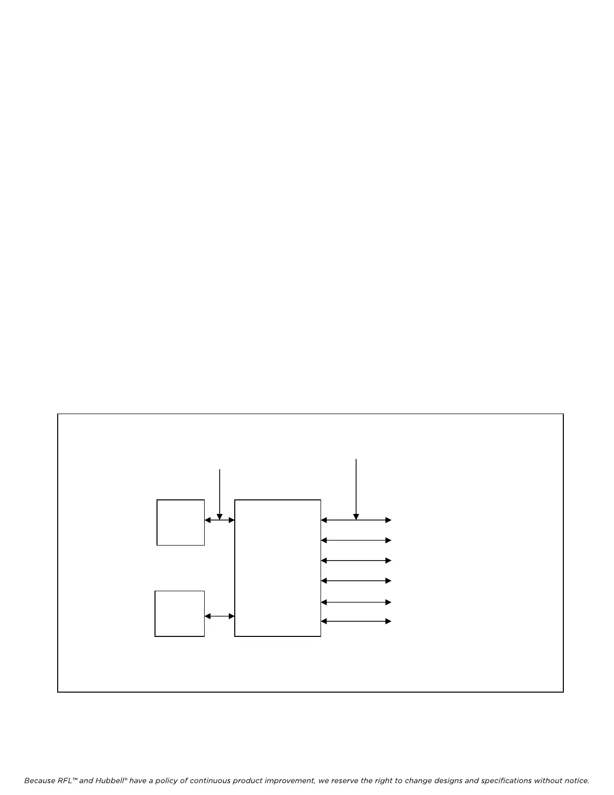
A typical M-DACS application has two sets of paths: six network paths which are connected either to
another T1 system or to a higher order multiplexer, and two paths (Port 5 & 6) connected to the CM4s.
These paths are shown in Figure 2-8. The DACS module monitors T1 data passing through it on its six
network paths and uses an alternate map if an error is detected on one of these network paths. The
DACS module will switch (if switching is enabled) from map 0 to one of the other alternate maps (1-7)
depending on which Map Select Criteria has been met. Map Select Criteria must be programmed by
the user using NMS as described in Section 5 of this manual. The DACS module uses programmable
and non-programmable criteria for error detection. The DACS module can also detect a recovery from
an error and will switch back to the primary map.
To perform these functions, the DACS module uses a microprocessor that monitors its internal
circuitry. It is programmable and can be monitored via the M-DACS Serial Control Bus. The DACS
module can operate in one of two modes: Super Frame (SF) and Extended Super Frame (ESF). See
paragraph 5.5.3.7.2 for information on how to program SF or ESF formats using NMS.
M-DACS-T1 RFL Electronics Inc.
Figure 2-8. DACS module paths and port numbers
DACS
Module
1
2
3
4
7
8
5
6
CM4
DI-A
CM4
DI-B
TWO PATHS
TO CM
4s
SIX NETWORK PATHS
TO ANOTHER
T1 SYSTEM OR A
HIGHER ORDER
MULTIPLEXER
October 16, 2012 2-10 (973) 334-3100