Because RFL™ and Hubbell® have a policy of continuous product improvement, we reserve the right to change designs and specifications without notice.
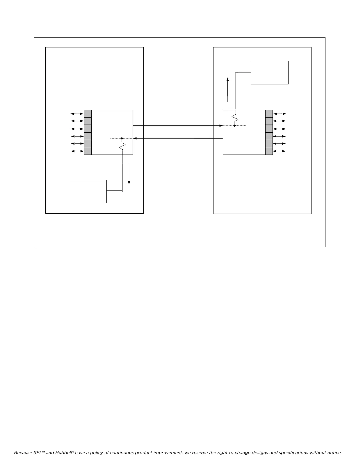
Monitoring the Location 2 to Location
1direction of transmission
Monitoring the Location 1 to Location 2
direction of transmission
T1
CIRCUIT
LOCATION 1
IMUX 2000
M-DACS
VOICE
AND
DATA
CIRCUITS
LOCATION 2
IMUX 2000
M-DACS
VOICE
AND
DATA
CIRCUITS
T1 TEST
SET
IN
T1 TEST
SET
IN
CM4
T1 IN
MON
CM4
T1 IN
MON
Figure 8-3. In-service monitoring of a T1 circuit
Use the following hints for interpreting test results:
1. On T1 systems using the ESF format, measure total CRC-6 errors, CRC-6 errorred seconds,
and CRC-6 severely errorred seconds to determine overall facility performance.
2. On systems using the SF format, frame bit error counts can indicate the presence of a high bit
error rate or severe error bursts. However, frame bit error monitoring cannot usually identify
problems with very low error rates.
3. Check with your service provider to determine what level of error performance is guaranteed
on your T1 circuit. Compare this with your actual test results.
M-DACS-T1 RFL Electronics Inc.
October 25, 2004 8-7 (973) 334-3100