Because RFL™ and Hubbell® have a policy of continuous product improvement, we reserve the right to change designs and specifications without notice.
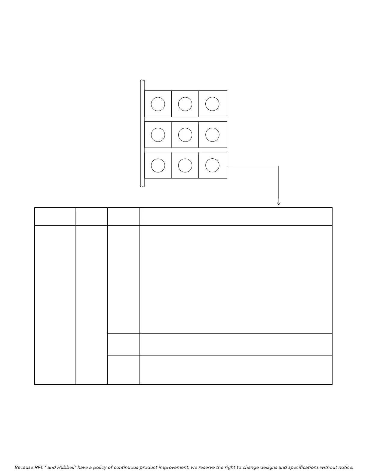
2.4.4.3 RX, BPV and FRM Indicators
Three LED indicators on the CM4 module (RX, BPV and FRM) indicate the status of the received T1
signal. The meaning of each of these indicators appears in Table 2-23.
M-DACS-T1 RFL Electronics Inc.
Table 2-22.
RX, BPV and FRM Indicators
Item
(Fig. 2-27)
Module Label Description
16 CM4 RX
Receive Input indicator (green); indicates receive status:
ON: A valid T1 data signal is detected at the CM4 T1 receiver
in
pu
t.
OFF:
No receive signal is detected.
BLINKING: One of the following signals or conditions is detected.
(Vi
ew the BLNK group, Paragraph 5.9, to determine
which condition is causing the blinking.)
Rx11: All ones produced by an idle shelf
at the far end, framed or
unframed.
RxY1: Yellow alarm, indicating a loss of receive
signal at the far
end, if the equipment at the far end is set up to generate
a yellow alarm.
XsJt: Excessive jitter, indicating that the jitter buffer depth has
been exceeded
.
FTIM The CM4 transmitter is in fallback internal timing mode.
BPV
Bipolar Variations indicator (yellow). Flashes once each time a bipolar
vi
olation is detected, and remains on continuously above a random BPV
(bipolar variations) error ratio of about 10
-5
.
FRM
Out-Of-Frame indicator (red). Lights when the CM4 T1 receiver is not in
frame sy
nchronization. This can indicate either a high bit error ratio, or
improper CM4 configuration.
G G G
LOOP INT EXT
G Y R
TX LPBK ERR
G Y R
RX BPV FRM
October 16, 2012 2-60 (973) 334-3100