Because RFL™ and Hubbell® have a policy of continuous product improvement, we reserve the right to change designs and specifications without notice.
2.2.7 INTELLIGENT LINE SWITCH (ILS) MODE OF OPERATION.
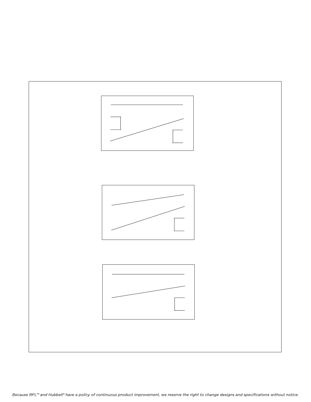
In ILS mode, normal signal routing is shown in Figure 2-6a. If there is a failure of Port 1, the DACS
module switches routing as shown in Figure 2-6b. If there is a failure of Port 4, the DACS module
switches routing as shown in Figure 2-6c.
Main Port 1
Backup Port 2
Backup Port 3
Main Port 4
5 Local Port
6 Local Port
7 Not Used
8 Not Used
2-6a. Normal mode routing of DACS module in Line-switch mode
2-6b. Switched upon failure of Port 1
Main Port 1
Backup Port 2
Backup Port 3
Main Port 4
5 Local Port
6 Local Port
7 Not Used
8 Not Used
Main Port 1
Backup Port 2
Backup Port 3
Main Port 4
5 Local Port
6 Local Port
7 Not Used
8 Not Used
2-6c. Switched upon failure of Port 4
Figure 2-6. Simplified diagram of DACS module in ILS mode.
M-DACS-T1 RFL Electronics Inc.
October 16, 2012 2-7 (973) 334-3100