Because RFL™ and Hubbell® have a policy of continuous product improvement, we reserve the right to change designs and specifications without notice.
5.5.3.7.1.1 T1 TIMING MODES
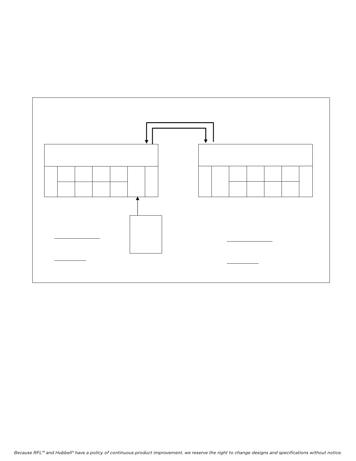
Appropriate uses of T1 transmitter timing modes for the M-DACS are illustrated in Figures 5-18
through 5-20. Note that in all the figures where the Master Timing is generated, if the DACS module
primary clock is set for “Int” then the secondary clock should be set for “ Not used”. If the primary
clock is set for “Ext” then the secondary clock should be set for “Int”.
NODE 1
NODE 2
T1 CIRCUIT
5
6
1
MA-
235
CM4
D/I-A
IMUX 2000 M-DACS
MULTIPLEXER
CM4
D/I-B
Node 2 M-DACS
Timing Setting
CM4s D/I-A & D/I-B
Primary Timing = THRU
Fallback Timing = Loop
DACS Module
Primary Clock = 1
=
5
6
1
MA-
235
CM4
D/I-A
IMUX 2000 M-DACS
MULTIPLEXER
CM4
D/I-B
Node 1 M-DACS
Timing Setting
CM4s D/I-A & D/I-B
Primary Timing = THRU
Fallback Timing = Loop
DACS Module
Primary Clock = Int. or Ext.
Secondar
Clock = Not used or Int.
STATION
CLOCK OR
OTHER
1.544 Mhz
TIMING
SOURCE
Figure 5-18. Point-to-point system timing setting
M-DACS-T1 RFL Electr
onics Inc.
February 28, 2006 5-29 (973) 334-3100