Because RFL™ and Hubbell® have a policy of continuous product improvement, we reserve the right to change designs and specifications without notice.
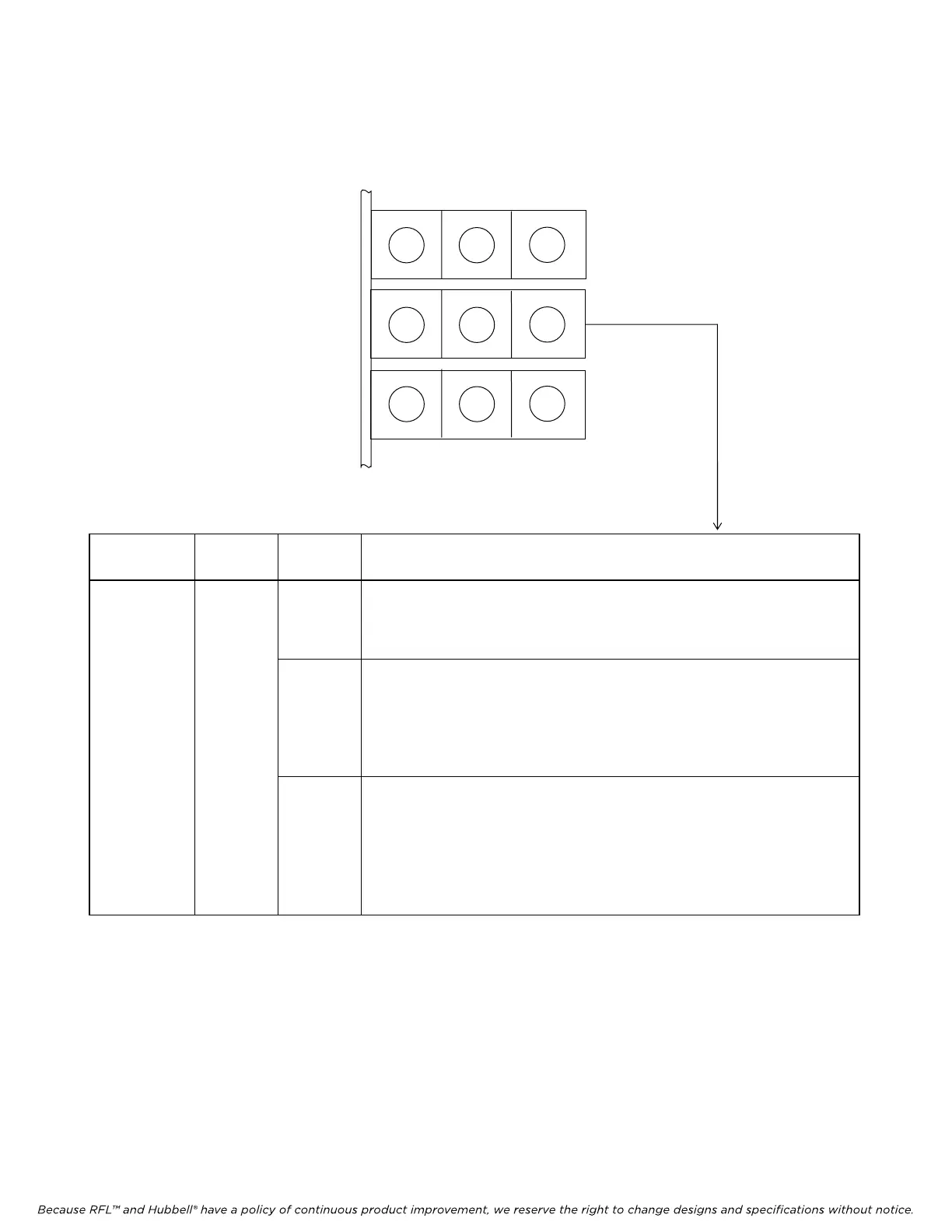
2.4.4.2 TX, LPBK and ERR Indicators
Three LED indicators on the CM4 module (TX, LPBK and ERR) indicate transmitter output status,
loopback status, and error status. The meaning of each of these indicators appears in Table 2-22.
M-DACS-T1 RFL Electronics Inc.
Table 2-21. TX, LPBK and ERR Indicators
Item
(Fig. 2-27)
Module Label Description
16 CM4 TX Transmit Output indicator (green); indicates transmit status:
ON: Transmission signal is normal. It can b
e
eith
er data, or all ones if the
shelf is idle.
OFF: No signal is being transmitted, indicating a hardware failure.
LPBK
Loopback indicator (yellow). Lights when one or more of the CM4’s three
T1 loo
pbacks have been activated. View the LPBK group to determine
The active loopback(s):
LNLB: Line Loopback
PaLB: Payload Loopback
EqLB: Equipment Loopback
ERR
Error indicator (red). When frame format is set to ESF, th
is indicator flashes
once each time a CRC-6 error is detected, and remains on continuously
above a random bit error ratio of about 10
-5
.
When
frame format is set to SF, this indicator flashes once each time a frame
error
is detected, and remains on continuously above a random bit error
ratio of about 10
-3
.
G G G
LOOP INT EXT
G Y R
TX LPBK ERR
G Y R
RX BPV FRM
October 16, 2012 2-59 (973) 334-3100