Because RFL™ and Hubbell® have a policy of continuous product improvement, we reserve the right to change designs and specifications without notice.
2.3.5.1 SERIAL PORTS
The I/O 2 serial port is configured as a DTE port using a male, DB-9 connector. The I/O 1 serial port is
configured as a DTE port using an RJ-12 connector which is similar to that used on the COM ports of
an IBM-compatible personal computer. Figure 2-22 shows the pin configuration of the I/O 1 port.
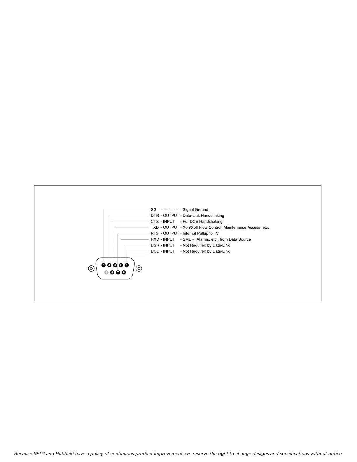
Figure 2-23 shows the pin configuration of the I/O 2 port.
The main pins which must be noted are the received data signal line on pin 2 and the signal ground on
pin 5. When receiving serial data, these are the only two connections which the SNMP Access
Gateway needs. However, if pass-through access to connected serial devices is required, then the
transmitted data signal line on pin 3 must be connected as well. Additionally, some equipment may
require an RS-232 high signal on one or more of its signal lines in order to transmit or accept data.
Consult the manual for your other equipment as needed.
The DCE, DB-9 female cable ends which mate with the serial port connectors of the SNMP Access
Gateway will often have a pair of screw-down cable locks. These cable locks should be used to assure
a solid connection of the cable with the SNMP Access Gateway serial port connectors.
Figure 2-23. SNMP Access Gateway DB9 Pin Out
M-DACS-T1 RFL Electronics Inc.
October 16, 2012 2-43 (973) 334-3100